11
Board Layout
Chapter 3
Embedded and Industrial Computing
Chapter 3:
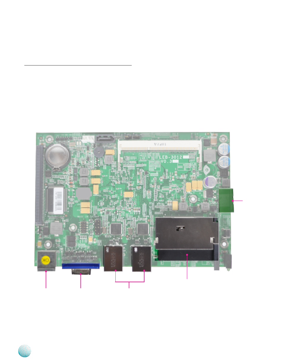
External Connectors
The following picture highlights the location of system
input/output connectors. Refer to the table 3.1 Connector
List for more details.
CN3
VGA1
CN2
LAN2/LAN1
CN1