Chapter 3: board layout, External connectors, Chapter 3 – Lanner LEC-7050 User Manual
Page 11: Board layout
Advertising
10
Board Layout
Chapter 3
Embedded and Industrial Computing
Chapter 3:
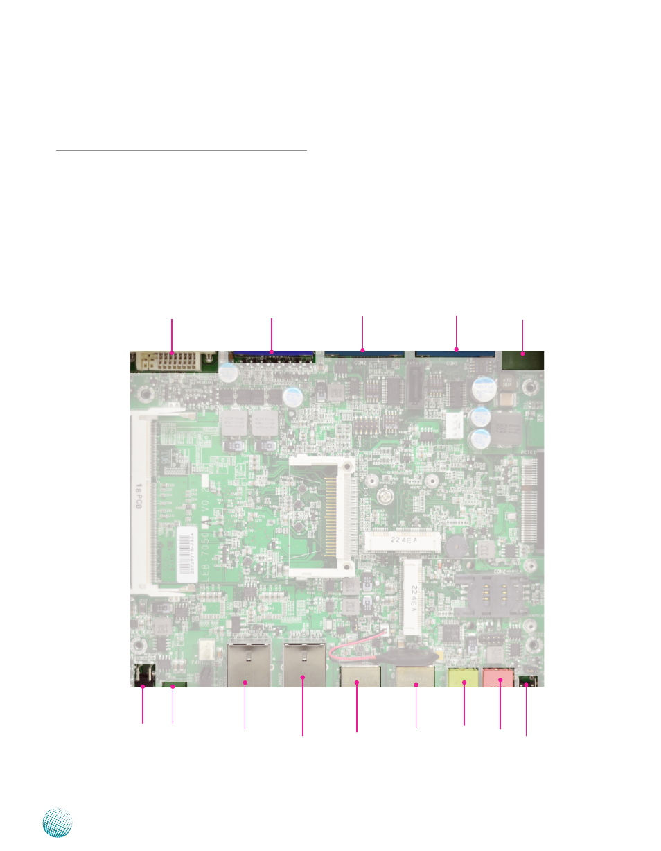
Board Layout
External Connectors
The following picture highlights the location of the
external ports. Refer to the table 3.1 Connector List for
more details.
LANB2
J3
U45
CN4
LANB1
UsB1
UsB2
sW5
J4
CN1
VGA1
COM2
COM1
CN2
Advertising