Chapter 3, Board layout, Terminating resistance tx, rx on – Lanner LEC-7050 User Manual
Page 15: Terminating resistance rx on, Terminating resistance off
14
Board Layout
Chapter 3
Embedded and Industrial Computing
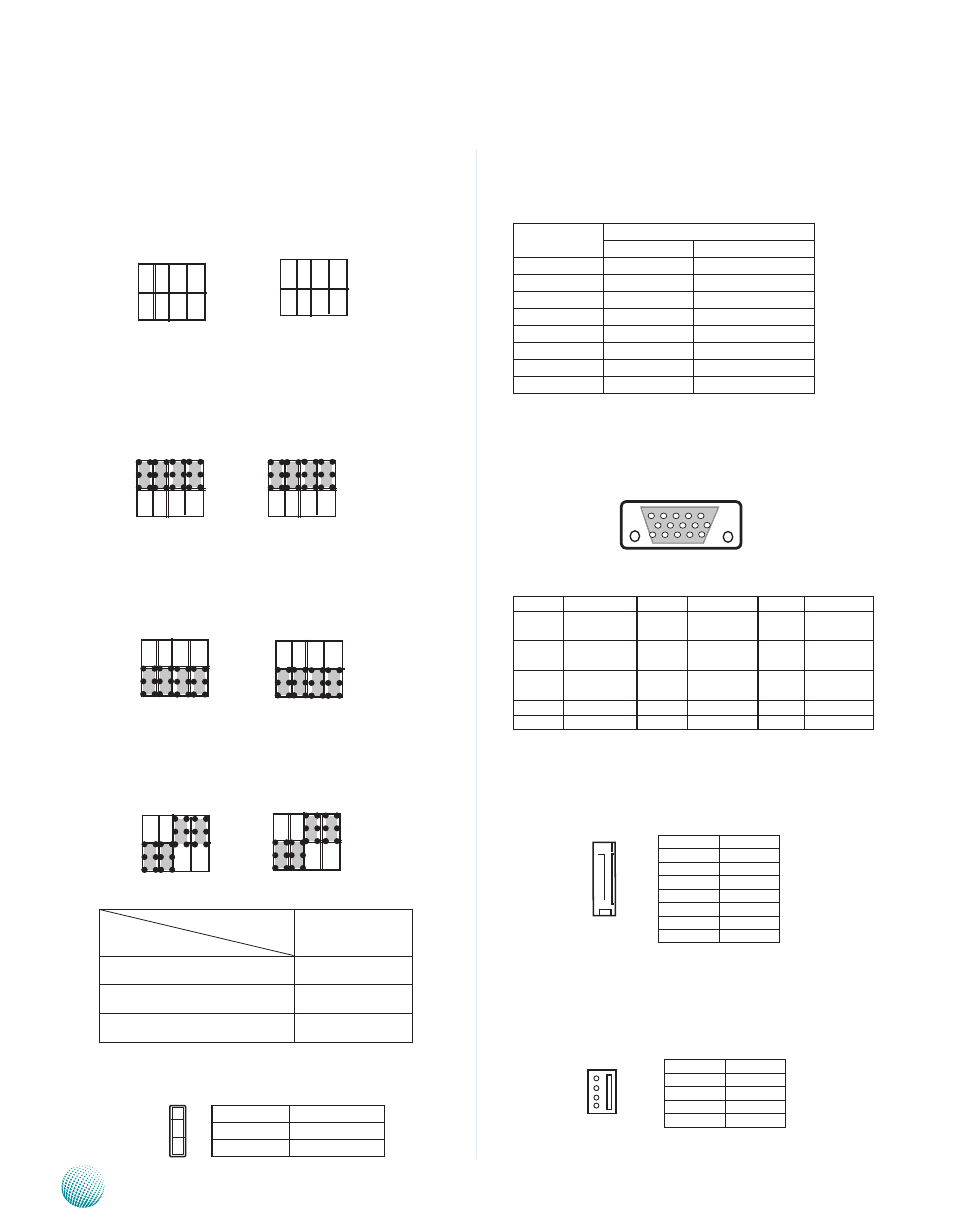
SW2: Select COM1 terminating resistance
SW3: Select COM2 terminating resistance
Clear CMOS jumper (JP1): It is for clearing the CMOS
settings.
LAN1/LAN2 Ports (LANB1/LANB2): The LAN ports are
provided by Intel 82583V Ethernet controller whose
interface complies with PCI-e 1.1 (2.5 Ghz). It supports PXE
remote boot as the advanced management feature
Pin No.
Description
Fast Ethernet Gigabit Ethernet
1
TX+
BI_DA+
2
TX-
BI_DA-
3
RX+
BI_DB+
4
--
BI_DC+
5
--
BI_DC-
6
RX-
BI_DB-
7
--
BI_DD+
8
--
BI_DD-
VGA (VGA1)
Pin
signal
Pin
signal
Pin
signal
1
Red Color
signal
6
GNd
11
NC
2
Green Color
signal
7
GNd
12
ddC dAT
3
Blue Color
signal
8
GNd
13
HsYNC
4
NC
9
VGA power
14
VsYNC
5
GNd
10
GNd
15
ddC CLK
Serial-ATA Connector (SATA1): It is for connecting a 2.5’’
harddisk to serve as your system’s storage. It can support
SATA II which features Data transfer rates up to 3.0 Gb/s
(300 MB/s).
4-pin Serial-ATA Power Connector (CON1): It is for
connecting the SATA power cord.
Pin No.
Pin Name
1-2
Normal (default)
2-3
Clear CMOs
3
2
1
15 14 13 12 11
5 4 3 2 1
Terminating resistance TX, RX on
sW2
sW3
Terminating resistance RX on
sW3
sW2
sATA1
Pin No.
Function
1
GNd
2
TX0_P
3
TX0_N
4
GNd
5
RX0_N
6
RX0_P
7
GNd
Pin No.
Function
1
+12V
2
GNd
3
GNd
4
+5V
1
2
3
4
SW2
4 3 2 1
SW3
4 3 2 1
ON
ON
Terminating resistance off
switch settings
Result
sW2/sW3
Terminating Resistance OFF
1,2,3,4 Off
Terminating Resistance TX, RX ON
1,2,3,4 On
Terminating Resistance RX on
1,2 Off
3,4 On