Front components, Chapter 2, System components – Lanner LEC-7105 User Manual
Page 8
8
System Components
Chapter 2
Embedded and Industrial Computing
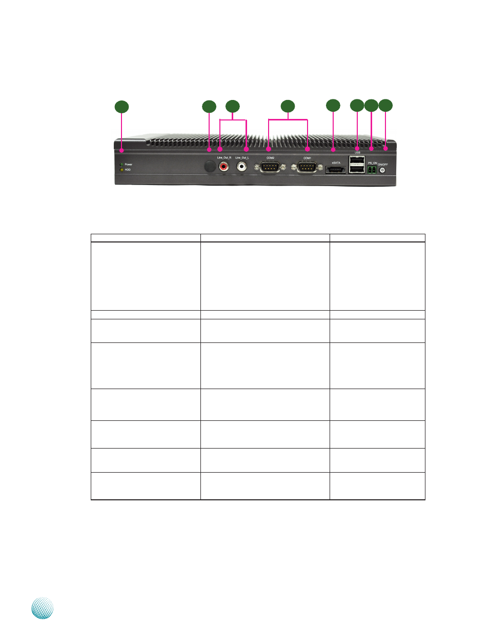
Front Components
Component
Description
Pin Definition Reference
F1 HDD (Yellow) and
Power LED (Green)
HDD
Blinking: data access activities
•
Off: no data access activities
•
Power
On: The computer is on.
•
Off: The computer is off .
•
F2 Antenna Hole
Reserved for antenna
F3 Line_Out_R
Line_Out_L
RCA Jack for audio output left and
right
CN1, CN2 on page 17
F4 Serial Ports 1 and 2
Serial ports through the DB-9
connector; COM1 supports RS-232
and COM2 supports RS-232/422/485
with switch selection among RS-
232/422/485.
COM1, COM2 on page 14
F5 Power eSATA
An external SATA connector with
5V power supply and support hot
plugging. It also supports USB 2.0
connection.
EUSB1 on page 14
F6 Dual USB Stack Connector
An USB type A connector; in addition to
this connector, an internal pin header is
provided.
Dual USB Port Connectors
(USB1, USB2) on Page16
F7 Power-on Switch
A power-on switch through the
Phoenix contact for distant power-on/
off control
J12 on page 16
F8 Power Button with dual LED ATX Power-on button with LEDs:
Standby mode in Red; Power-on mode
in Green
F1
F2
F4
F6
F3
F5
F7
F8