Development kit demonstration software example – Linx Technologies MDEV-xxx-DT User Manual
Page 11
– –
– –
16
17
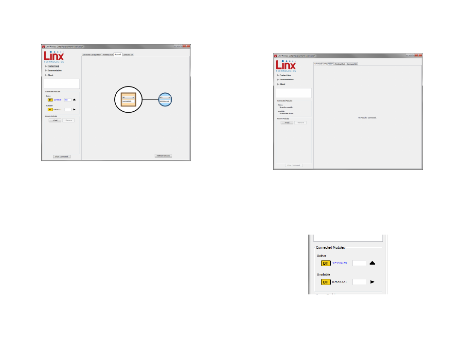
The Network tab shows the interaction of all of the connected modules
on one screen. Figure 19 shows two modules on the screen, but up to 8
modules can fit at one time.
The screen shows the network configuration of all modules that are
connected to the PC. The drop-down menu changes the module’s device
type and the text box has the module’s network ID. This screen makes it
easy to quickly set up the network and visually verify its configuration.
Figure 19: The Master Development System Software Network Tab
Development Kit Demonstration Software Example
This example shows how to configure two modules to work with each
other. The software defaults to the Advanced Configuration tab when
opened (Figure 20).
Install Carrier Boards onto the Programming Docks and plug a USB cable
between the Programming Docks and the PC. The software automatically
detects attached devices. The first module that is identified appears
under the Active label. This is the module that is actively controlled by
the software. Subsequent modules are listed under the Available label as
shown in Figure 21.
Once the modules are detected by the software, the appropriate options
are displayed on the Advanced Configurations tab and a Network tab
appears. The module’s documents appear under the Documentation link.
Figure 20: The Master Development System Software Advanced Configuration Tab at Start-up
Figure 21: The Master Development System Software Connected Modules