Prototype board, Prototype board objects, Initial setup – Linx Technologies MDEV-xxx-DT User Manual
Page 5
– –
– –
4
5
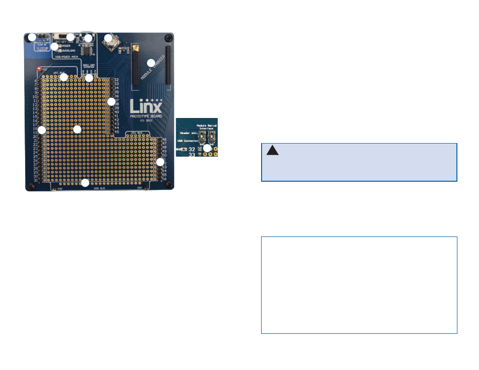
Prototype Board
Prototype Board Objects
1. Carrier Board Socket
2. RP-SMA Antenna Connector
3. Micro USB Connector
4. Power Switch
5. Power LED
6. External Battery Connection
7. Prototyping Area
8. 3.3V Supply Bus
9. Ground Bus
10. USB Interface Lines
11. Module Interface Headers
12. Command Data Interface Routing Switches (on back)
Figure 6: Prototype Board
4
1
2
3
10
6
7
8
11
5
9
11
11
12
Initial Setup
There are several boards that are included with the Development System.
The Carrier Boards have a HumDT
TM
Series transceiver on a daughter
board with headers. These boards snap into sockets on the other boards,
enabling the modules to be easily moved among the test boards.
There are two Programming Docks that have a socket for a Carrier
Board and a USB interface for connection to a PC. This is used with the
demonstration software included with the kit to configure the module
through its Command Data Interface.
There are two Prototype Boards that have a socket for a Carrier Board, a
USB interface and a large area of plated through holes that can be used to
develop custom circuitry. The board can be powered either from the USB
connection or an external battery.
The development software supports Windows XP, Vista, 7, 8, and 8.1;
OS X 10.6 ‘Snow Leopard’ or later (including Lion, Mountain Lion, and
Mavericks); any version of Linux with Java 1.6 or later.
Warning:
Installing or removing a Carrier Board while power is
applied could cause permanent damage to the module. Either turn
off power to the board or unplug the USB cable before installing or
removing a Carrier Board
!
Note:
The Prototype board uses a USB to UART chip to connect the
module to the PC. This chip is powered from the 5V on the USB cable.
It has an input line that detects the voltage on Vcc and sets the UART
voltage levels to match as soon as power is applied to the chip.
It is important that the power switch (SW3) be set appropriately before
the USB cable is plugged in. If an external power supply is used and the
switch is off when the cable is plugged in, then the UART output voltage
may not be set correctly and could result in communication failures.
Set the switch to BAT when using an external supply or to USB to use
the USB bus to power the module. Then plug in the USB cable.