Using the programming dock – Linx Technologies MDEV-xxx-DT User Manual
Page 7
– –
– –
8
9
Using the Programming Dock
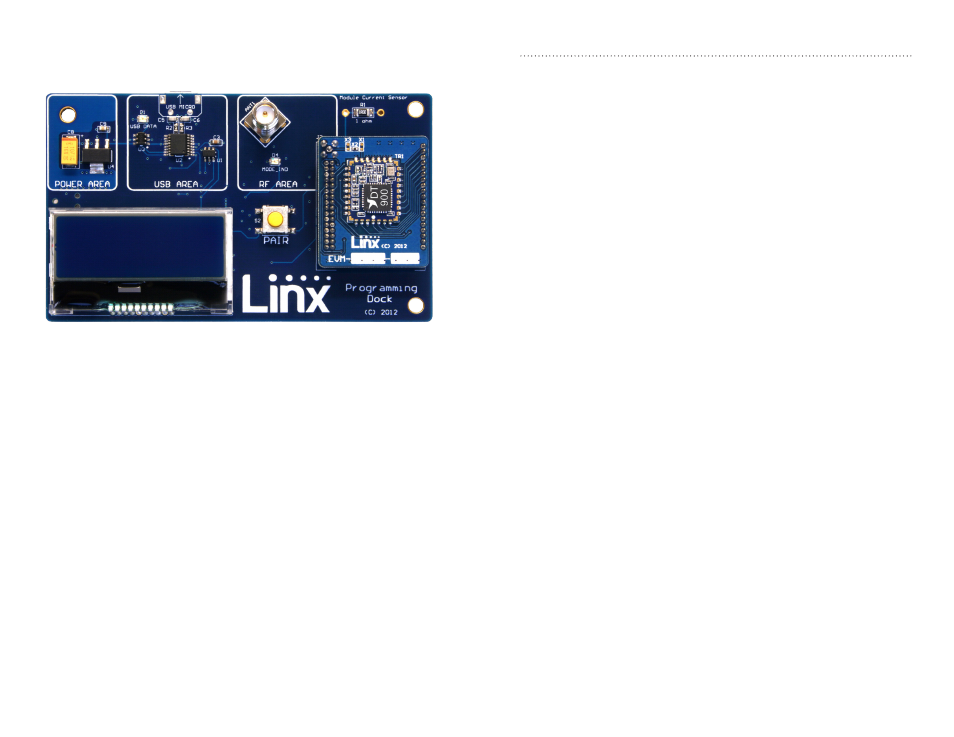
Snap a Carrier Board onto the socket on the Programming Dock as shown
in Figure 9.
Connect a micro USB cable into the connector at the top of the board.
Plug the other end into a PC. The board is powered by the USB bus.
The demonstration software included with the kit or custom application
software can be used to configure the module through its Command
Data Interface. The LCD is used to display information about the module.
This includes the module’s local address and a custom nickname. The
nickname is entered using the development kit software and can be
any name that helps distinguish the modules from one another. This is
convenient when multiple programming docks are connected to the same
computer. Please see the development kit software section for more
information on the nicknames.
The HumDT
TM
Series transceiver has a serial Command Data Interface that
is used to configure and control the transceiver. This interface consists of a
standard UART with a serial command set.
Figure 9: Programming Dock with a Carrier Board
Range Testing
Several complex mathematical models exist for determining path loss in
many environments. These models vary as the transmitter and receiver are
moved from indoor operation to outdoor operation. Although these models
can provide an estimation of range performance in the field, the most
reliable method is to simply perform range tests using the modules in the
intended operational environment.
Range testing can be performed with the Programming Docks and / or
the Prototype Boards. Data can be sent across the link using the included
software or a custom microcontroller connected to the module. The RSSI is
included with the output data messages, so this can be used to qualify the
link.
As the maximum range of the link in the test area is approached, it is not
uncommon for the signal to cut in and out as the radio moves. This is
normal and can result from other interfering sources or fluctuating signal
levels due to multipath effects. This results in cancellation of the transmitted
signal as direct and reflected signals arrive at the receiver at differing times
and phases. The areas in which this occurs are commonly called “nulls”
and simply walking a little farther usually restores the signal. If the signal is
not restored, then the maximum range of the link has been reached.
To achieve maximum range, keep objects such as your hand away from
the antenna and ensure that the antenna on the transmitter has a clear and
unobstructed line-of-sight path to the receiver board. Range performance
is determined by many interdependent factors. If the range you are able to
achieve is significantly less than specified by Linx for the products you are
testing, then there is likely a problem with either the board or the ambient
RF environment in which the board is operating. First, check the battery,
switch positions, and antenna connection. Next, check the ambient RSSI
value with the transmitter turned off to determine if ambient interference
is present. High RSSI readings while the transmitter off indicate there is
interference. If this fails to resolve the issue, please contact Linx technical
support.