Linx Technologies MDEV-xxx-DT User Manual
Page 13
– –
– –
20
21
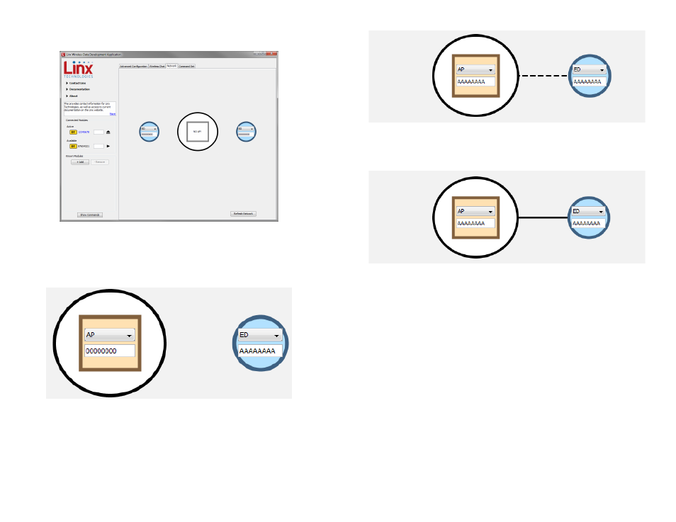
A dotted line appears between the modules indicating that they are joining
the network.
A solid line appears between the modules when they are joined and ready
to communicate. The Wireless Chat tab can now be used to send data
between the modules.
Figure 27: The Master Development System Software Network Tab
Figure 28: The Master Development System Software Network Tab
Clicking on the Network tab shows the current state of all modules
connected to the PC.
Both modules are set as End Devices. There must be at least one
Access Point in every network, so one module must be changed. This is
accomplished by clicking the drop-down menu on one of the modules and
selecting AP.
Both modules must have the same Network ID, so change the ID number
in one or both of the boxes to match.
Figure 25: The Master Development System Software Network Tab
Figure 26: The Master Development System Software Network Tab