Transferring data, Typical applications – Linx Technologies TRM-xxx-LT User Manual
Page 11
– –
– –
16
17
Transferring Data
Once a reliable RF link has been established, the challenge becomes how
to effectively transfer data across it. While a properly designed RF link
provides reliable data transfer under most conditions, there are still distinct
differences from a wired link that must be addressed. The LT Series is
intended to be as transparent as possible and does not incorporate internal
encoding or decoding, so a user has tremendous flexibility in how data is
handled.
If the product transfers simple control or status signals such as button
presses or switch closures and it does not have a microprocessor on board
(or it is desired to avoid protocol development), consider using a remote
control encoder and decoder or a transcoder IC. These chips are available
from a wide range of manufacturers including Linx. They take care of all
encoding and decoding functions, and generally provide a number of data
pins to which switches can be directly connected. In addition, address bits
are usually provided for security and to allow the addressing of multiple
units independently. These ICs are an excellent way to bring basic remote
control / status products to market quickly and inexpensively. Additionally,
it is a simple task to interface with inexpensive microprocessors, IR, remote
control or modem ICs.
It is always important to separate the types of transmissions that are
technically possible from those that are legally allowable in the country
of intended operation. Linx Application Notes AN-00125, AN-00128
and AN-00140 should be reviewed, along with Part 15, Section 231 of
the Code of Federal Regulations for further details regarding acceptable
transmission content in the US All of these documents can be downloaded
from the Linx website at www.linxtechnologies.com.
Another area of consideration is that the data structure can affect the
output power level. The FCC allows output power in the 260 to 470MHz
band to be averaged over a 100ms time frame. Because OOK modulation
activates the carrier for a ‘1’ and deactivates the carrier for a ‘0’, a data
stream that sends more ‘0’s has a lower average output power over
100ms. This allows the instantaneous output power to be increased, thus
extending range.
Typical Applications
The LT Series transceiver does not perform any encoding or decoding of
the data, so the designer has a great deal of flexibility in the design of a
protocol for the system. The data source and destination can be any device
that uses asynchronous serial data such as a PC or a microcontroller. If the
application is for remote control or command, then the easiest solution is
to use a remote control encoder and decoder. These ICs provide a number
of data lines that can be connected to switches or buttons or even a
microcontroller. When a line is taken high on the encoder, a corresponding
line goes high on the decoder as long as the address matches. The Linx
MT Series transcoder is an encoder and decoder in a single chip which
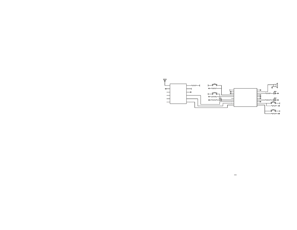
allows bidirectional control and confirmation using a transceiver. Figure 23
shows a circuit using the Linx LICAL-TRC-MT transcoder.
The MT Series has eight data lines, which can be set as inputs and
connected to buttons that pull the line high when pressed, or set as
outputs to activate external circuitry. When not used, the lines are pulled
low by 100k-ohm resistors. The transcoder begins a transmission when
any of the input data lines are taken high. When a valid transmission is
received, the transcoder activates the appropriate output data lines and
then sends a confirmation back to the originating transcoder. When the
confirmation is received, the originating transcoder activates its CONFIRM
line. In this example, this turns on an LED for visual indication. The
transcoder automatically controls the power to the transceiver via the PDN
line and the transmit / receive state via the T/R_SEL line.
The MT Series transcoder data guide explains this circuit and the features
of the transcoder in detail, so please refer to that for more information.
A 750-ohm resistor is used on the LADJ line of the transceiver to reduce
the output power of the transmitter to meet North American certification
requirements. This value may need to be adjusted depending on antenna
efficiency and the power allowed in the country of operation.
GND
VCC
GND
GND
750 ohm
100K
VCC
GND
GND
GND
100k
GND
VCC
VCC
D6
D7
CRT/LRN
ENC SEL
SER IO
CONFIRM
T/R PDN
T/R SEL
T/R DATA
D0
D1
D2
MODE IND
BAUD SEL
LATCH
D3
D4
D5
GND
LICAL-TRC-MT
GND
200 ohm
GND
200 ohm
RF
1
GND
2
NC
3
RSSI
4
A REF
5
ANALOG
6
DATA
7
T/R SEL
8
PDN
9
GND
10
VCC
11
LADJ
12
TRM-XXX-LT
GND
VCC
VCC
GND
100k
VCC
GND
100k
VCC
BUZZER
GND
GND
GND
GND
200 ohm
GND
Figure 23: LT Series Transceiver and MT Series Transcoder