Module description, Theory of operation – Linx Technologies TRM-xxx-LT User Manual
Page 8
– –
– –
10
11
Module Description
The LT Series transceiver is a low-cost, high-performance synthesized
AM OOK transceiver capable of transmitting and receiving serial data at
up to 10,000bps over line-of-site distances of up to 3,000 feet (1000m).
Its exceptional receiver sensitivity and highly stable transmitter output
result in outstanding range performance. The transceiver is completely
self-contained and does not require any additional RF components except
an antenna. This greatly simplifies the design process, reduces time to
market, and reduces production assembly and testing costs. The LT
is housed in a compact surface-mount package that integrates easily
into existing designs and is equally friendly to prototyping and volume
production. The module’s low power consumption makes it ideal for
battery-powered products.
Theory of Operation
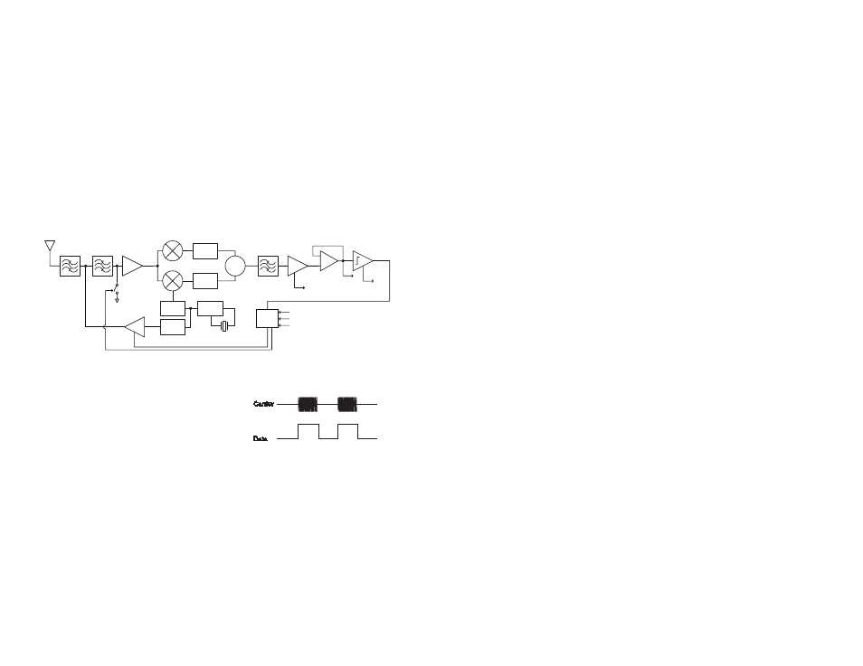
The LT Series transceiver sends and
recovers data by AM or Carrier-Present
Carrier-Absent (CPCA) modulation, also
referred to as On-Off Keying (OOK). This
type of modulation represents a logic low
‘0’ by the absence of a carrier and a logic high ‘1’ by the presence of a
carrier (Figure 20). This method affords numerous benefits. The two most
important are: 1) cost-effectiveness due to design simplicity and 2) higher
legally-allowable output power and thus greater range in countries (such as
the US) that average output power measurements over time.
The LT’s receiver chain utilizes an advanced synthesized superheterodyne
architecture and achieves exceptional sensitivity. Transmitted signals
enter the module through a 50-ohm RF port intended for single-ended
connection to an external antenna. RF signals entering the antenna are
filtered and then amplified by an NMOS cascode Low Noise Amplifier
(LNA). The signal is then down-converted to a 10.7MHz Intermediate
Frequency (IF) by mixing it with a low-side Local Oscillator (LO). The LO
frequency is generated by a Voltage Controlled Oscillator (VCO) which is
locked by a Phase-Locked Loop (PLL) frequency synthesizer referenced
to a precision crystal. The mixer stage is a pair of double-balanced mixers
and a unique image rejection circuit, which greatly reduces susceptibility to
interference. The IF frequency is further amplified, filtered, and demodulated
to recover the original signal. The signal is squared by a data slicer and
output on the DATA line.
The LT’s transmitter chain is designed to generate up to 10mW of output
power into a 50-ohm single-ended antenna while suppressing harmonics
and spurious emissions. The transmitter is comprised of a VCO locked
by the PLL. The output of the VCO is amplified and buffered by a power
amplifier. The amplifier is switched by the incoming data to produce a
modulated carrier. The internal digital logic controls a switch that connects
the LNA input to ground when in transmit mode, preventing the transmitter
from de-sensitizing the receiver. The carrier is filtered to attenuate
harmonics, and then output on the 50-ohm RF port.
The transceiver’s topology makes the module highly immune to frequency
pulling, mismatch, temperature, and other negative effects common
to some low-cost architectures. The LT Series design and component
quality enable it to outperform many far more expensive transceiver
products, making it well-suited for a wide range of consumer and industrial
applications.
Data Slicer
LNA
RX VCO
PLL
XTAL
0°
90°
Limiter
RX Data
Analog
∑
10.7MHz
IF Filter
Band Select
Filter
50
Ω RF IN
(Antenna)
+
-
Digital
Logic
TX VCO
RSSI
A REF
PA
PDN
T/R SEL
DATA
GND
Figure 19: LT Series Transceiver Block Diagram
Carrier
ON
OFF
Data
Figure 20: CPCA (AM) Modulation