Ordering information, Absolute maximum ratings, Electrical specifications – Linx Technologies TRM-xxx-LT User Manual
Page 4: Electrical specifications ordering information
– –
– –
2
3
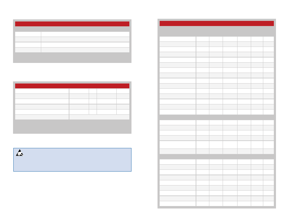
LT Series Transceiver Specifications
Parameter
Symbol
Min.
Typ.
Max.
Units
Notes
Power Supply
Operating Voltage
V
CC
2.1
3.0
3.6
VDC
Supply Current
l
CC
TX Mode Logic High
12
14
mA
1
TX Mode Logic High
7.6
9.5
mA
2
TX Mode Logic Low
4.0
5.0
mA
Receive Mode
6.1
7.9
mA
Power Down Current
l
PDN
11.5
20.0
µA
9,10
DATA Line
Output Low Voltage
V
OL
0.15
VDC
3
Output High Voltage
V
OH
V
CC
–0.26
VDC
4
Input Low Threshold
V
IL
0.1 V
CC
VDC
5
Input High Threshold
V
IH
0.9 V
CC
VDC
Power Down Input
Input Low Threshold
V
IL
0.1 V
CC
VDC
5
Input High Threshold
V
IH
0.9 V
CC
VDC
RF Section
Frequency Range
F
C
TRM-315-LT
315
MHz
TRM-418-LT
418
MHz
TRM-433-LT
433.92
MHz
Center Frequency
Accuracy
–50
+50
kHz
Data Rate
65
10,000
bps
Receiver Section
LO Feedthrough
–80
dBm
6,9
IF Frequency
F
IF
10.7
MHz
9
Noise Bandwidth
N
3DB
280
kHz
9
Receiver Sensitivity
–108
–112
–118
dBm
7
RSSI / Analog
Dynamic Range
80
dB
9
Analog Bandwidth
20
5,000
Hz
9
Gain
15
mV/dB
9
Voltage with No Carrier
430
mV
9
Electrical Specifications
Ordering Information
Ordering Information
Part Number
Description
TRM-315-LT
315MHz Transceiver
TRM-418-LT
418MHz Transceiver
TRM-433-LT
433MHz Transceiver
EVAL-***-LT
Basic Evaluation Kit
*** =
315, 418 (Standard), 433MHz
Transceivers are supplied in tubes of 18 pcs.
Absolute Maximum Ratings
Figure 2: Ordering Information
Absolute Maximum Ratings
Supply Voltage V
cc
−0.3
to
+4.0
VDC
Any Input or Output Pin
−0.3
to
V
CC
+ 0.3
VDC
RF Input
0
dBm
Operating Temperature
−40
to
+85
ºC
Storage Temperature
−65
to
+150
ºC
Soldering Temperature
+260ºC for 10 seconds
Exceeding any of the limits of this section may lead to permanent damage to the device.
Furthermore, extended operation at these maximum ratings may reduce the life of this
device.
Figure 3: Absolute Maximum Ratings
Warning:
This product incorporates numerous static-sensitive
components. Always wear an ESD wrist strap and observe proper ESD
handling procedures when working with this device. Failure to observe
this precaution may result in module damage or failure.