Absolute maximum ratings, Typical performance graphs – Linx Technologies RXM-xxx-ES User Manual
Page 5
Advertising
– –
– –
4
5
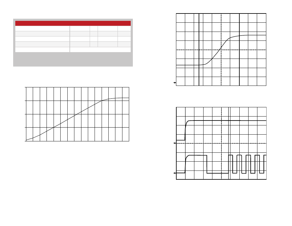
Typical Performance Graphs
Figure 5: RSSI Characteristics Chart
Figure 6: Worst Case RSSI Response Time
-110
-100
-90
-80
-70
-60
-50
-40
RF Input (dBm)
1.0
1.5
2.0
2.5
3.0
RSSI Voltage (V)
1
CH1 500mV 1mS
RX Off
RX On >-35dBm
Figure 7: Rx V
CC
to Valid Data
1
2
CH1 2.00V CH2 2.00mV 1mS
Supply
RX Data
Absolute Maximum Ratings
Supply Voltage V
cc
−0.3
to
+5.5
VDC
Any Input or Output Pin
−0.3
to
V
CC
+ 0.3
VDC
Operating Temperature
0
to
+70
ºC
Storage Temperature
–40
to
+125
ºC
Soldering Temperature
260ºC for 15 seconds
Exceeding any of the limits of this section may lead to permanent damage to the device.
Furthermore, extended operation at these maximum ratings may reduce the life of this
device.
Absolute Maximum Ratings
Figure 4: Absolute Maximum Ratings
Advertising