Pin assignments, Pin descriptions, Data in audio out – Linx Technologies RXM-xxx-ES User Manual
Page 6
– –
– –
6
7
Pin Assignments
Figure 9: ES Series Receiver Pinout (Top View)
Pin Descriptions
Pin Number
Name
I/O Description
1
ANT
—
50-ohm RF Input
2
GND
—
Analog Ground
3
NC
—
No Electrical Connection. Soldered for
physical support only.
4
GND
—
Analog Ground
5
V
CC
—
Supply Voltage
6–9
NC
—
No Electrical Connection. Soldered for
physical support only.
10
A REF
O
Audio RMS (Average) Voltage Reference
11
AUDIO
O
Recovered Analog Output
12
DATA
O
Digital Data Output. This line outputs the
demodulated digital data
13
RSSI
O
Received Signal Strength Indicator. This
line outputs an analog voltage that is
proportional to the strength of the received
signal.
14
PDN
I
Power Down. Pulling this line low places the
receiver into a low-current state. The module
is not able to receive a signal in this state.
15–16
NC
—
No Electrical Connection. Soldered for
physical support only.
Pin Descriptions
Figure 10: ES Series Transmitter Pin Descriptions
ANT
GND
NC
PDN
RSSI
DATA
AUDIO
A REF
NC
NC
GND
VCC
NC
NC
NC
NC
1
2
3
4
5
6
7
8
9
10
11
12
13
14
15
16
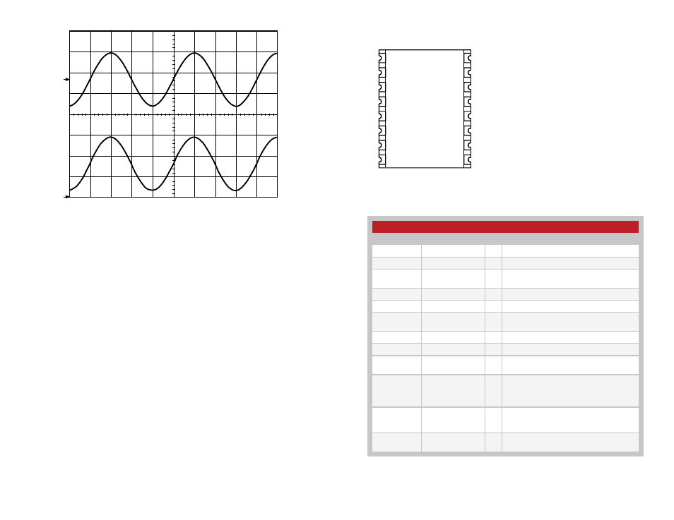
Figure 8: Sine-Wave Modulation Linearity
CH1 396mV CH2 100mV 250uS
1
2
DATA IN
AUDIO OUT