Module description, Theory of operation, Using the pdn line – Linx Technologies RXM-xxx-ES User Manual
Page 7: Esd concerns
– –
– –
8
9
Module Description
The ES Series receiver module is a single-channel receiver designed for
the wireless reception of digital or analog information over distances of
up to 1,000 feet outdoors and up to 500 feet indoors. It is based on a
high-performance, synthesized, single conversion, superhet architecture.
FM / FSK modulation and SAW filtering are utilized to provide performance
and noise immunity that are superior to AM-based solutions. The ES series
is incredibly compact and cost effective when compared with other FM /
FSK devices. Best of all, it is packed with many useful features, offering a
great deal of design flexibility.
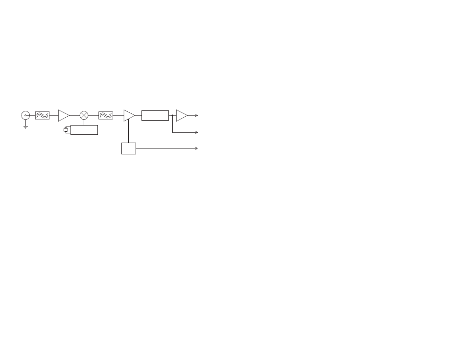
Theory of Operation
The receiver operates in a single conversion superhet configuration, with an
IF of 10.7MHz and a baseband analog bandwidth of 28kHz. It is capable
of receiving a signal as low as –97dBm (typical). The signal is filtered at the
front end by a SAW band-pass filter. The filtered signal is then amplified
and downconverted to the 10.7MHz IF by mixing it with a LO frequency
generated by a PLL-locked VCO. The 10.7MHz IF is then amplified and
filtered. Finally, a PLL demodulator is used to recover the baseband analog
signal from the carrier. This analog signal is low-pass filtered and then
output on the AUDIO line.
The analog output can be individual frequencies or complex waveforms,
such as voice or music. The AUDIO line can also be used to recover
unsquared data in instances where a designer wishes to use an external
data slicer.
The ES receiver also features a high-performance on-board data slicer
for recovery of data transmission. Its output is internally derived from
the filtered analog baseband, which is squared and made externally
available on the DATA line. The data slicer is capable of recreating squared
waveforms from 100Hz to 28kHz, giving a data rate bandwidth of 200bps
to 56kbps.
Figure 11: ES Series Receiver Block Diagram
It is important to note that this receiver does not provide hysteresis or
squelching of the DATA line. This means that in the absence of a valid
transmission or transitional data, the DATA line switches randomly. The
effects of this noise must be considered and will be discussed in further
detail later in this guide.
The receiver features a Received Signal Strength Indicator (RSSI) output.
The RSSI pin outputs a linear voltage relative to the incoming signal level.
This output has many valuable uses, including interference assessment,
signal strength indication, external data squelching and qualification, and
transmitter presence indication. Since RSSI values vary from part to part
and correspond to signal strength and not necessarily distance, it is not
recommended for range-finding applications.
Using the PDN Line
The Power Down (PDN) line can be used to power down the receiver
without the need for an external switch. This line has an internal pull-up, so
when it is held high or simply left floating, the module is active.
When the PDN line is pulled to ground, the receiver enters into a
low-current (<50µA) power-down mode. During this time the receiver is off
and cannot perform any function. It may be useful to note that the startup
time coming out of power-down is slightly less than when applying V
CC
.
The PDN line allows easy control of the receiver state from external
components, like a microcontroller. By periodically activating the receiver,
checking for data, then powering down, the receiver’s average current
consumption can be greatly reduced, saving power in battery-operated
applications.
ESD Concerns
The module has basic ESD protection built in, but in cases where the
antenna connection is exposed to the user it is a good idea to add
additional protection. A Transient Voltage Suppressor (TVS) diode, varistor
or similar component can be added to the antenna line. These should have
low capacitance and be designed for use on antennas. Protection on the
supply line is a good idea in designs that have a user-accessible power
port.
RF In
SAW BPF
LNA
Limiter
Precision
Crystal
PLL Frequency
Synthesizer
PLL
Demodulator
10.7MHz
IF Filter
Data
Slicer
Peak
Detector
RSSI
Output
Audio
Output
Data
Output