Caution, Electrical specifications, Absolute maximum ratings – Linx Technologies RXM-GPS-SR User Manual
Page 2: Pin assignments, Pin # name i/o description, Pin descriptions
ELECTRICAL SPECIFICATIONS
*CAUTION*
This product incorporates numerous static-sensitive components.
Always wear an ESD wrist strap and observe proper ESD handling
procedures when working with this device. Failure to observe this
precaution may result in module damage or failure.
ABSOLUTE MAXIMUM RATINGS
Supply Voltage V
CC
+5.5
VDC
Input Battery Backup Voltage
+7.0
VDC
Operating Temperature
-30
to
+85
°C
Storage Temperature
-40
to
+85
°C
Soldering Temperature
+225°C for 10 seconds
*NOTE*
Exceeding any of the limits of this section may lead to permanent
damage to the device. Furthermore, extended operation at these maximum
ratings may reduce the life of this device.
Table 1: SR Series Receiver Specifications
Parameter
Designation
Min.
Typical
Max.
Units
Notes
POWER SUPPLY
Supply Voltage
V
CC
3.0
–
4.3
VDC
–
Supply Current:
I
CC
1
Peak
–
31
49
mA
–
Sleep
–
<0.1
–
mA
–
Backup Battery Voltage
V
BAT
1.3
–
6.0
VDC
–
Backup Battery Current
I
BAT
–
10
–
µA
–
Output Logic Low Voltage
V
OL
–
–
0.73
VDC
–
Output Logic High Voltage
V
OH
2.0
–
–
VDC
–
Output Logic Low Current
I
OL
–
2
–
mA
–
Output Logic High Current
I
OH
–
2
–
mA
–
Input Logic Low Voltage
V
IL
-0.3
–
0.8
VDC
–
Input Logic High Voltage
V
IH
2.1
–
3.6
VDC
–
Input Logic Low Current
I
IL
-10
–
60
µA
–
Input Logic High Current
I
IH
-10
–
60
µA
–
ENABLE Logic Low Voltage
V
IL
–
–
0.25
VDC
–
ENABLE Logic High Voltage
V
IH
1.3
–
Vcc
VDC
–
ENABLE Logic Low Current
I
IL
-0.2
–
1
µA
–
ENABLE Logic High Current
I
IH
-0.2
–
10
µA
–
ENVIRONMENTAL
Operating Temperature Range
–
-30
–
+85
°
C
–
Storage Temperature Range
–
-40
25
+85
°
C
–
RECEIVER SECTION
Acquisition Time
Hot Start (Open Sky)
–
–
2
S
–
Cold Start
–
35
–
S
–
Position Accuracy
Autonomous
–
–
10
m
–
SBAS
–
–
5
m
–
Altitude
–
–
60,000
ft
–
Velocity
–
–
1,000
Knots
–
Chipset
SiRF Star III, GSC3f/LPx 7990
Firmware Version
GSW3.5.0_3.5.00.00-SDK-3EP2.01A
Frequency
L1 1575.42MHz, C/A Code
Channels
20
Update Rate
1Hz
Protocol Support
NMEA 0183 ver 3.0, SiRF Binary
Page 2
Page 3
Notes:
1. V
CC
= 3.3V
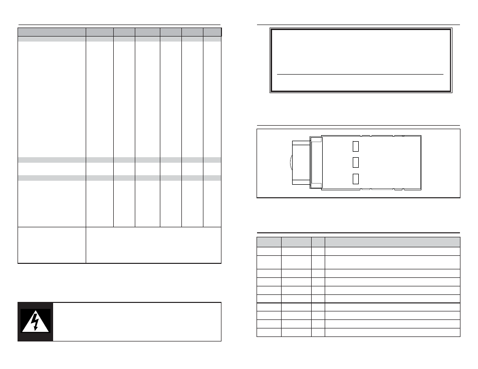
PIN ASSIGNMENTS
10
1
2
3
45
6
7
8
9
GND
VBACKUP
TX
RX
GND
GND
LED
NC
EN
VCC
Figure 2: SR Series Receiver Pinout (Top View)
Pin #
Name I/O
Description
1
GND
P
Ground
2
VBACKUP
P
Backup battery supply voltage. This line must be
powered to enable the module.
3
TX
O
Serial Data Output (default NMEA)
4
RX
I
Serial Data Input (default NMEA)
5
LED
O
LED Indicator (100k
Ω internal pull-down)
6
NC
No Electrical Connection
7
EN
I
Enable (active high, internal pull-down)
8
VCC
P
Supply Voltage
9
GND
P
Ground
10
GND
P
Ground
PIN DESCRIPTIONS