Typical applications, Slow start time, Power control – Linx Technologies RXM-GPS-SR User Manual
Page 4
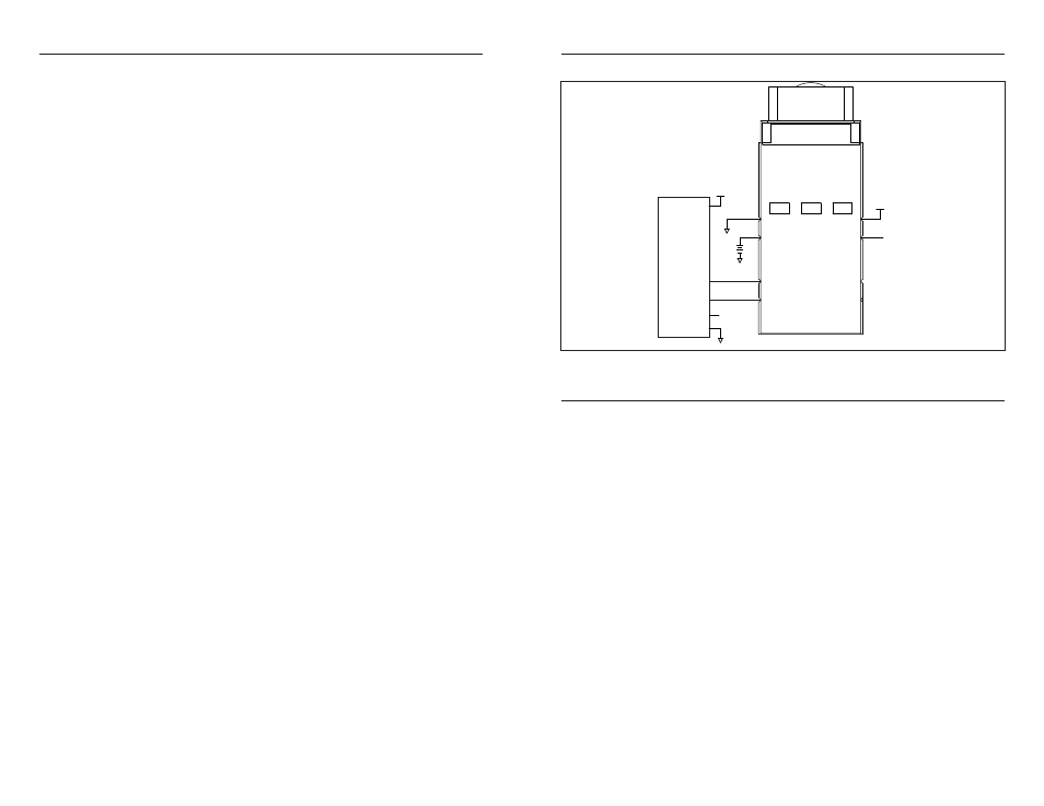
TYPICAL APPLICATIONS
Figure 4 shows a typical application for the module.
SLOW START TIME
The most critical factors in start time are current ephemeris data, signal strength,
and sky view. The ephemeris data describes the path of each satellite as they
orbit the earth. This is used to calculate the position of a satellite at a particular
time. This data is only usable for a short period of time, so if it has been more
than a few hours since the last fix or if the location has significantly changed (a
few hundred miles), then the receiver may need to wait for a new ephemeris
transmission before a position can be calculated. The GPS satellites transmit
the ephemeris data every 30 seconds. Transmissions with a low signal strength
may not be received correctly or be corrupted by ambient noise. The view of the
sky is important because the more satellites the receiver can see, the faster the
fix and the more accurate the position will be when the fix is obtained.
If the receiver is in a very poor location, such as inside a building, urban canyon,
or dense foliage, then the time to first fix can be slowed. In very poor locations
with poor signal strength and a limited view of the sky with outdated ephemeris
data, this could be on the order of several minutes. In the worst cases, the
receiver may need to receive almanac data, which describes the health and
course data for every satellite in the constellation. This data is transmitted every
15 minutes. If a lock is taking a long time, try to find a location with a better view
of the sky and fewer obstructions. Once locked, it is easier for the receiver to
maintain the position fix.
Page 6
Page 7
POWER CONTROL
By default, the SR Series will operate in full power mode. However, it also has a
built-in power control mode called Adaptive Trickle Power mode. In this mode,
the receiver will power on at full power to acquire and track satellites and obtain
satellite data. It then powers off the RF stage and only uses its processor stage
(CPU) to determine a position fix (which takes about 160mS). Once the fix is
obtained, the receiver goes into a low power standby state. After a user-defined
period of time, the receiver wakes up to track the satellites for a user-defined
period of time, updates its position using the CPU only, and then resumes stand-
by. The initial acquisition time is variable, depending on whether it is a cold start
or assisted, but a maximum acquisition time is definable. This cycling of power
is ideal for battery-powered applications since it significantly reduces the amount
of power consumed by the receiver while still providing similar performance to
the full power mode.
In normal conditions, this mode provides a fixed power savings, but under poor
signal conditions, the receiver returns to full power to improve performance. The
receiver sorts the satellites according to signal strength and if the fourth satellite
is below 26dB-Hz, then the receiver switches to full power. Once the fourth
satellite is above 30dB-Hz, the receiver returns to Adaptive Trickle Power mode.
For optimum performance, SiRF recommends cycle times of 300mS track to 1S
interval or 400mS track to 2S interval. CPU time is about 160mS to compute the
navigation solution and empty the UART. There are some situations in which the
receiver stays in full power mode. These are: to collect periodic ephemeris data,
to collect periodic ionospheric data, to perform RTC convergence, and to
improve the navigation result. Depending on states of the power management,
the receiver will be in one of three system states:
Full Power State
All RF and baseband circuitry are fully powered. There is a difference in power
consumption during acquisition mode and tracking mode. Acquisition requires
more processing, so it consumes more power. This is the initial state of the
receiver and it stays in this state until a reliable position solution is achieved.
CPU Only State
This state is entered when the satellite measurements have been collected but
the navigation solution still needs to be computed. The RF and DSP processing
are no longer needed and can be turned off.
Stand-By State
In this state, the RF section is completely powered off and the clock to the
baseband is stopped. About 1mA of current is drawn in this state for the internal
core regulator, RTC and battery-backed RAM. The receiver enters this state
when a position fix has been computed and reported.
µP
TX
RX
GND
VCC
GND
GND
VCC
ENABLE
GND
10
1
2
3
4
5
6
7
8
9
GND
VBACKUP
TX
RX
GND
GND
LED
NC
EN
VCC
VCC
ENABLE
ENABLE
Figure 3: SR Series Module Typical Application