Nmea output messages, Protocols, Interfacing with nmea messages – Linx Technologies RXM-GPS-SR User Manual
Page 5
Page 9
Page 8
NMEA OUTPUT MESSAGES
The following sections outline the data structures of the various NMEA protocols
that are supported by the module. By default, the NMEA commands are output
at 9,600bps, 8 data bits, no parity, and 1 stop bit.
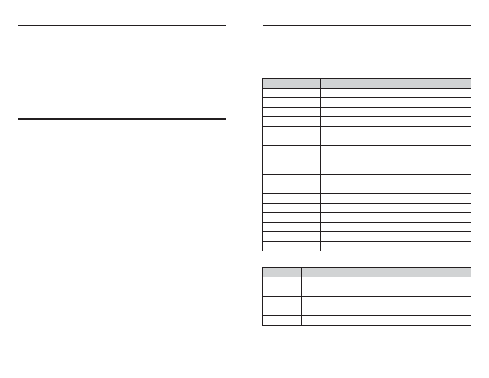
GGA – Global Positioning System Fixed Data
The table below contains the values for the following example:
$GPGGA,053740.000,2503.6319,N,12136.0099,E,1,08,1.1,63.8,M,15.2,M,,0000*64
Name
Example
Units
Description
Message ID
$GPGGA
GGA protocol header
UTC Time
053740
hhmmss.sss
Latitude
2503.6319
ddmm.mmmm
N/S indicator
N
N=north or S=south
Longitude
12136.0099
dddmm.mmmm
E/W Indicator
E
E=east or W=west
Position Fix Indicator
1
See Table 4
Satellites Used
08
Range 0 to 12
HDOP
1.1
Horizontal Dilution of Precision
MSL Altitude
63.8
meters
Units
M
meters
Geoid Separation
15.2
meters
Units
M
meters
Age of Diff. Corr.
second Null fields when DGPS is not used
Diff. Ref. Station
ID 0000
Checksum
*64
<CR> <LF>
End of message termination
Value
Description
0
Fix not available or invalid
1
GPS SPS Mode, fix valid
2
Differential GPS, SPS Mode, fix valid
3-5
Not supported
6
Dead Reckoning Mode, fix valid
Table 2: Global Positioning System Fixed Data Example
Table 3: Position Indicator Values
PROTOCOLS
LINX GPS modules use the SiRFstar III chipset. This chipset allows two
protocols to be used, NMEA-0183 and SiRF Binary. Switching between the two
is handled using a single serial command. The NMEA protocol uses ASCII
characters for the input and output messages and provides the most common
features of GPS development in a small command set. The SiRF Binary protocol
uses BYTE data types and allows more detailed control over the GPS receiver
and its functionality using a much larger command set. Although both protocols
have selectable baud rates, it’s recommended that SiRF Binary use baud rates
of 38,400bps or higher. For a detailed description of the SiRF Binary protocol,
see the SiRF Binary Protocol Reference Manual, available from SiRF
Technology, Inc. Although SiRF Binary protocol may be used with the module,
Linx only offers tech support for the NMEA protocol.
INTERFACING WITH NMEA MESSAGES
Linx modules default to the NMEA protocol. Output messages are sent from the
receiver on the TX pin and input messages are sent to the receiver on the RX
pin. By default, output messages are sent once every second. Details of each
message are described in the following sections.
The NMEA message format is as follows: <Message-ID + Data Payload +
Checksum + End Sequence>. The serial data structure defaults to 9,600bps, 8
data bits, 1 stop bit, and no parity bits. Each message starts with a $ character
and ends with a <CR> <LF>. All fields within each message are separated by a
comma. The checksum follows the * character and is the last two characters, not
including the <CR> <LF>. It consists of two hex digits representing the exclusive
or (XOR) of all characters between, but not including, the $ and * characters.
When reading NMEA output messages, if a field has no value assigned to it, the
comma will still be placed following the previous comma. For example,
{,04,,,,,2.0,} shows four empty fields between values 04 and 2.0. When writing
NMEA input messages, all fields are required, none are optional. An empty field
will invalidate the message and it will be ignored.
Reading NMEA output messages:
• Initialize a serial interface to match the serial data structure of the GPS receiver.
• Read the NMEA data from the TX pin into a receive buffer.
• Separate it into six buffers, one for each message type. Use the characters ($)
and <CR> <LF> as end points for each message.
• For each message, calculate the checksum as mentioned above to compare
with the checksum received.
• Parse the data from each message using commas as field separators.
• Update the application with the parsed field values.
• Clear the receive buffer and be ready for the next set of NMEA messages.
Writing NMEA input messages:
• Initialize a serial interface to match the serial data structure of the GPS receiver.
• Assemble the message to be sent with the calculated checksum.
• Transmit the message to the receiver on the RX pin.