Curtis RACP1206 User Manual
Page 5
5
6
IDENTIFICATION OF PARTS
NAMES OF PARTS
Fig.2
Front
Operation Panel
Horizontal Louver Blade
(swing automatically)
Caster
Carrying Handle
(both sides)
1
2
3
4
1
2
3
4
1
2
3
4
5
Model A
Model B
Operation Panel
Horizontal Louver Blade
(manually)
Remote signal receptor
Caster
Carrying Handle
(both sides)
1
2
3
4
5
Fig.1
Fig.3
Rear
9
6
7
8
10
11
6
7
8
9
10
11
Upper Air Filter
(Behind the grille)
Air Outlet
Power cord outlet
Air intake
Drain Outlet
Air intake
Lower Air Filter
(Behind the grille)
Bottom tray drain outlet
12
12
13
13
AIR CONDITIONER FEATURES
Before you begin, thoroughly familiarize yourself with the control panel and remote controller
and all its functions, then follow the symbol for the functions you desire.
The unit can be controlled by the unit control panel alone or with the remote controller .
ELECTRONIC CONTROL OPERATING INSTRUCTIONS
Fig.4
NOTE: This manual does not include Remote Controller Operations, see the <<Remote
Controller Instruction>> packed with the unit for details.
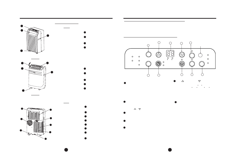
OPERATION PANEL OF THE AIR CONDITIONER
6
2
3
4
5
7
8
1
Selects the appropriate operating mode.
Each time you press the button, a mode
is selected in a sequence that goes from
AUTO, COOL, DRY, FAN and HEAT(cooling
only models without). The mode indicator light
illuminates under the different mode settings
Fig.4.
MODE select button
1
Used to adjust (increasing/decreasing)
temperature settings(1 C/2 F increments)
in a range of 17 C(62 F) to 30 C(88 F) or
the TIMER setting in a range of 0~24hrs..
6
UP( ) and DOWN( ) button
NOTE: The control is capable of displaying
temperature in degrees Fahrenheit or degrees
Celsius. To convert from one to the other, press
and hold the Up and Down buttons at the same
time, for 3 seconds.
3
Used to initiate the AUTO ON start time and
AUTO OFF stop time program, in conjuction
with the & buttons.
TIMER button
4
Used to initiate the SLEEP operation.
SLEEP button
6
2
Power switch on/off.
POWER button
AUTO
HEAT
COOL
DRY
FAN
MODE
ION
SLEEP
FAN
HI
MED
LOW
TIMER ON
TIMER OFF
F
C
5
FAN button
7
O
Shows the set temperature in C
O
" F" and the Auto-timer settings.
While on DRY and FAN modes, it shows
the room temperature.
"
" or
LED Display
SWING
Remote signal receptor
(Some models have the
signal receptor on the
front panel , Fig.2)
9
(The model has no
auto swing feature
withou t this button)
Control the fan speed. Press to select the fan
speed in four steps-LOW, MED, HI and AUTO.
The fan speed indicator light illuminates under
different fan settings except AUTO speed. When
select AUTO fan speed, all the fan indicator lights
turn dark.
Error codes and protection code:
E1- Room temperature sensor error-
Unplug the unit and plug it back in.
If error repeats, call for service.
E2- Evaporator temperature sensor error-
Unplug the unit and plug it back in.
If error repeats, call for service.
E4- Display panel communication error-
Unplug the unit and plug it back in.
If error repeats, call for service.
P1- Bottom tray is full - Connect the
drain hose and drain the collected
water away. If error repeats, call
for service.