Fig.1, Fig.3, Fig.4 fig.2 – Sealey MIGHTYMIG170 User Manual
Page 3: Assembly & preparation
SPECIFICATION, Model No: ......................................................MIGHTYMIG170
Maximum Current: ......................................................................................... 170A
Wire Capacity steel: ..........................................................................................5kg
duty Cycle: .......................100% @ 55Amps, 60% @ 70Amps, 15% @ 140Amps
Cooling System: ..................................................................................... Forced Air
Gas Type: .................................................................CO², Argon & CO²/Argon mix
Torch: ................................................................ euro Non live - BINZel ® MB15
Power Input ............................................................................................. 230V 1ph
Absorbed power ........................................................................................... 5.4kW
Case size ...................................................................................................... large
Weight ..........................................................................................................41.5kg
SPECIFICATION, Model No: . . . . . . . . . . . . . . . . . . . . . . . . . . .MIGHTYMIG190
Maximum Current: . . . . . . . . . . . . . . . . . . . . . . . . . . . . . . . . . . . . . . . . . . . . 190A
Wire Capacity steel: . . . . . . . . . . . . . . . . . . . . . . . . . . . . . . . . . . . . . . . . . .5-15kg
duty Cycle: . . . . . . . . . . .100% @ 70Amps, 60% @ 90Amps, 15% @ 180Amps
Cooling System: . . . . . . . . . . . . . . . . . . . . . . . . . . . . . . . . . . . . . . . . . . Forced Air
Gas Type: .................................................................CO², Argon & CO²/Argon mix
Torch: . . . . . . . . . . . . . . . . . . . . . . . . . . . . . . . euro Non live - BINZel ® MB15
Power Input . . . . . . . . . . . . . . . . . . . . . . . . . . . . . . . . . . . . . . . . . . . . . . 230V 1ph
Absorbed power . . . . . . . . . . . . . . . . . . . . . . . . . . . . . . . . . . . . . . . . . . . . . 7.2kW
Case size . . . . . . . . . . . . . . . . . . . . . . . . . . . . . . . . . . . . . . . . . . . . . . . . . . large
Weight . . . . . . . . . . . . . . . . . . . . . . . . . . . . . . . . . . . . . . . . . . . . . . . . . . . . .43.5kg
SPECIFICATION, Model No: . . . . . . . . . . . . . . . . . . . . . . . . . . .MIGHTYMIG210
Maximum Current: . . . . . . . . . . . . . . . . . . . . . . . . . . . . . . . . . . . . . . . . . . . . 210A
Wire Capacity steel: . . . . . . . . . . . . . . . . . . . . . . . . . . . . . . . . . . . . . . . . . .5-15kg
duty Cycle: . . . . . . . . . .100% @ 80Amps, 60% @ 105Amps, 15% @ 210Amps
Cooling System: . . . . . . . . . . . . . . . . . . . . . . . . . . . . . . . . . . . . . . . . . . Forced Air
Gas Type: .................................................................CO², Argon & CO²/Argon mix
Torch: . . . . . . . . . . . . . . . . . . . . . . . . . . . . . . . euro Non live - BINZel ® MB15
Power Input . . . . . . . . . . . . . . . . . . . . . . . . . . . . . . . . . . . . . . . . . . . . . . 230V 1ph
Absorbed power . . . . . . . . . . . . . . . . . . . . . . . . . . . . . . . . . . . . . . . . . . . . . 9.0kW
Case size . . . . . . . . . . . . . . . . . . . . . . . . . . . . . . . . . . . . . . . . . . . . . . . . . . large
Weight . . . . . . . . . . . . . . . . . . . . . . . . . . . . . . . . . . . . . . . . . . . . . . . . . . . . .45.5kg
3. ASSEMBLY & PREPARATION
fig.1
3.1
ASSEMBLING THE WHEELS: (Refer to fig.1) The wheels are more
easily assembled with the welder placed upside down on a smooth
non-abrasive surface. The welder should be turned over by two people
as it is very heavy.
3.1.1
Bolt the two castors (1) to the front end of the base (2) using the bolts
provided.
3.1.2
Take the solid axle (3) and slide a wheel (4) over one end followed by a
washer (5). Insert a split pin (6) through the hole in one end of the axle
as shown below and bend it over.
3.1.3
Take an axle retaining bracket (7) and insert it into the slots in the base
(2). Hold the bracket in place and slide the axle assembly through both
parts of the bracket. Insert the second axle retaining bracket (7) through
the base and continue to slide the axle across so that it passes through
the second bracket and holds the wheel (4) up against the side of the
base. Slide the second wheel (8) onto the free end of the axle followed by
a washer (9). Retain the entire axle assembly by passing a split pin (10)
through the free end of the axle and bend it over to retain the whole axle
assembly.
3.1.4
With the assistance of another person turn the welder the right way up
onto its wheels.
3.2
ASSEMBLING THE HANDLE: (Refer to fig.2) On the front of the welder
there are two pairs of threaded inserts, one pair in the top left corner and
one pair in the top right hand corner..
3.2.1
Attach the left hand handle mounting (1) to the front of the welder using
two of the 25mm round headed bolts provided. do not fully tighten yet.
3.2.2
Slide the handle tube (2) into the socket in the mounting and push fully
home.
3.2.3
Slide the socket on the right hand handle mounting (3) over the free end
of the handle tube and rotate the mounting downwards until it is resting
on the front of the welder. Using two of the 25mm round headed bolts
provided to fix the right hand mounting in place.
3.2.4
Now fully tighten all four fixings.
3.3
ASSEMBLING THE EARTH CLAMP: (Refer to fig.3) Feed the eyelet on the
end of the earth lead through the hole in the clamp arm as shown in fig.3A.
3.3.1
drop the eyelet over the terminal and firmly fix with the bolt provided as
shown in fig.3B.
fig.3
3.4
INSTALLING THE GAS CYLINDER. The welder is designed to
accommodate small or medium sized gas cylinders up to a maximum
height of 1000mm. Contact your local Gas dealer for supply.
3.4.1
Place the gas cylinder onto the rear platform of the welder. drop one
end of the fixing chain into one side of the retaining bracket. draw
the chain around the cylinder and place it into the slot on the other
side of the bracket leaving as little slack in the chain as possible.
3.5
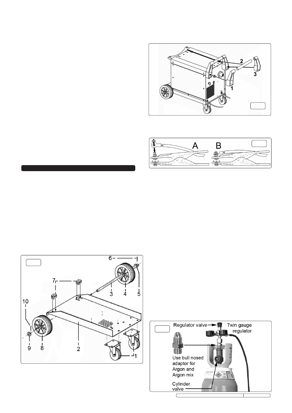
ATTACHING THE REGULATOR. Whichever gas you are using it is
advisable to 'crack' the cylinder valve before attaching the regulator.
This means opening and closing the valve very quickly in order to
blow away any dust and dirt that may have accumulated in the gas
outlet. Stand to one side whilst doing this.
3.5.1
CO² GAS. ensure that the threads on the gas bottle are undamaged
and free of oil and grease before attaching the regulator. (Oil or
grease in the presence of high pressure gases can be explosive.)
ensure that the regulator has an undamaged gasket fitted. The
regulator will screw directly to the threads on the gas bottle. Tighten
with a spanner.
3.5.2
ARGON GAS OR ARGON MIxTURES. Cylinders containing Argon
gas and Argon mixtures have a female thread and will require the use
of a Bull Nose Adaptor to attach the regulator to the cylinder as
indicated in fig.4. ensure that the threads on the gas bottle are
undamaged and free of oil and grease before attaching the regulator.
(Oil or grease in the presence of high pressure gases is explosive.)
Fit the Bull Nose Adaptor to the cylinder first and tighten with a
spanner. ensure that the regulator has an undamaged gasket before
fitting onto the Bull Nose Adaptor. Tighten with a spanner.
3.5.3
Slide a jubilee clip over each end of the gas hose supplied. Push
one end of the hose onto the regulator outlet and the other end over
the gas inlet spigot on the back of the welder. Tighten the clips to
ensure a good seal.
3.5.4
Close the regulator valve by turning it anticlockwise before opening
the cylinder valve. Stand to one side when opening the cylinder valve.
3.5.5
Set the regulator flow rate to 5-8 litres/min depending on the
material to be welded, and whether there are draughts which are
strong enough to disturb the gas flow.
fig.4
fig.2
Original Language Version
MIGHTYMIG170, MIGHTYMIG190, MIGHTMIG210 Issue: 2 - 26/02/10