Fig.15 – Sealey MIGHTYMIG170 User Manual
Page 5
3.10
SETTING WIRE TENSION. Adjust the wire tension by rotating the
wire tension knob. Turn clockwise to increase the tension and
anticlockwise to decrease the tension. See (1) in fig13.
IMPORTANT: Too little or too much tension will cause problematic
wire feed and result in poor welding.
3.10.1 Tension between rollers is checked by slowing down the wire between
gloved fingers. If top feed roller skids the tension is correct. Use as
low a tension as possible, too high a tension will disfigure wire and
result in a blown fuse.
3.11
CLUTCH ADJUSTMENT. Note: It is essential that the clutch is adjusted
correctly.
3.11.1 Once the wire is fed through the torch, switch on the machine and set
the wire speed to maximum.
3.11.2 depress torch switch and release quickly. If the spool overruns it
indicates that the clutch is too loose.
3.11.3 Tighten the clutch nut located in the centre of the wire spool holder
with a spanner (fig.8-C) and test the machine as above until the wire
stops over running.
Note: dO NOT over tighten the clutch as this will cause wire feed
problems and strain the motor.
(Mightytmig170 is preset and has no direct clutch adjustment.)
3.12
TURNING/CHANGING THE DRIVE ROLLER. (See fig.14) ensure
that the wire diameter used, is matched by the correct groove size in
the drive wheel and the correct tip size on the torch as well as the
correct torch liner. Failure to do this could cause the wire to slip and/
or bind.
3.12.1 Referring to fig.11, open the wire feed mechanism by pushing the
locking/wire tension knob (1) down to the right allowing the pressure
roller carrier (2) to spring up revealing the feed roller.
3.12.2 Referring to fig.14, loosen and unscrew the black feed roller retaining
knob (C) and put to one side.
3.12.3 The roller carrier (A) is keyed to the main drive shaft and the drive
roller (B) is keyed to the carrier, see below. Place a finger onto the
end of the drive shaft to prevent the carrier moving and slide the drive
roller off the carrier with your other hand.
3.12.4 The size of each wire feed groove is printed on the edge of the roller
on the same side as the groove.
3.12.5 Turn the roller over to use the other groove or use a roller with
different sized grooves as required. The groove to be used should be
positioned furthest away from you to be in line with the drive path.
3.12.6 Check that the key in the carrier (A) is properly seated in its slot.
ensure that the slot on the inside face of the drive roller (B) is aligned
with the key and slide the roller back onto the carrier.
3.12.7 Screw the black roller retaining knob (C) back on to the end of the
drive shaft and tighten.
3.9.5 Check welder is switched off “0”, and that the earth clamp is away
from the torch tip. Connect the welder to the mains power supply and
set the voltage switch to one.
3.9.6 Set the wire speed knob to position 5 or 6. Keep the torch cable as
straight as possible and press the torch switch. The wire will feed
through the torch.
3.9.7
When the wire has fed through, switch welder off, unplug from mains.
a) Take torch in left hand, slide the contact tip over the wire and screw
back into place.
b) Grasp gas cup in right hand, push onto torch head and turn
clockwise only. do not turn gas cup anti-clockwise, as this will
damage the internal spring.
c) Cut wire so that it is just protruding from the cup.
fig.11
fig.14
fig.13
fig.12
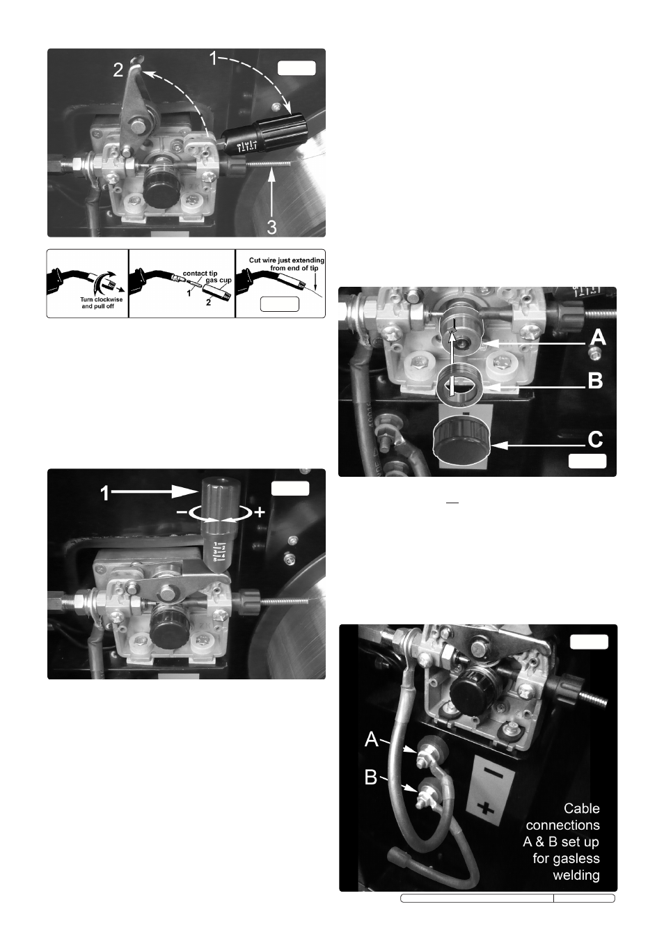
3.13
CONVERTING TO GASLESS WELDING. When delivered, your
welder is set up for gas welding with the torch cable connected to
the positive (+) terminal and the earthing cable connected to the
negative (-) terminal.
3.13.1
To weld without gas (using flux cored wire) you must reverse
the polarity and connect the torch cable to the negative (-)
terminal and the earthing cable to the positive (+) terminal as
shown below in fig.15.
3.13.1
Ensure that the machine is switched off and unplugged from
the mains supply before carring our this task.
3.13.2
Safely disconnect the gas.
3.13.3
Fit a 1.0mm tip to the torch.
3.13.4
Change the drive roller to one having a 1.0mm groove.
3.13.5
Mount the flux cored wire reel and feed it through to the torch.
fig.15
Original Language Version
MIGHTYMIG170, MIGHTYMIG190, MIGHTMIG210 Issue: 2 - 26/02/10