Mig/mag welding, Ratings plate, Wire 0.6mm steel argon / co2 mix – Sealey MIGHTYMIG170 User Manual
Page 6
A spool of welding wire is positioned on the welder’s spool holder and
automatically fed through an insulated liner in the torch to the tip. The torch
assembly consists of a switch, liner, gas hose, and control cable. The switch
activates the wire feed roller and the gas flow. Conversely, releasing the switch
stops the wire feed and gas flow. The weld current is transferred to the
electrode (the wire) from the contact tip at the end of the torch. A gas cup fits
over the contact tip to direct the gas flow towards the weld ensuring that the
arc welding process is shielded from oxidising air contaminates. The shielding
gas also assists heating of the weld materials. (The welder can also be used in
gasless mode using flux cored wire). The torch is connected to the positive
side of a dC rectifier, and the negative clamp is attached to the workpiece.
IMPORTANT: Should you have no welding experience, we recommend
you seek training from an expert source to ensure your personal health &
safety. Good Mig welding may be achieved only with continued,
supervised practice.
4. 1
PREPARATION FOR WELDING
IMPORTANT: BEFORE YOU COMMENCE, MAKE SURE THE
MACHINE IS SWITCHED OFF AT THE MAINS. IF WELDING A CAR,
DISCONNECT THE BATTERY OR FIT AN ELECTRONIC CIRCUIT
PROTECTOR. WE STRONGLY RECOMMEND THE USE OF
SEALEY “PROSAF/12V OR 24V IN ORDER TO PROTECT
SOPHISTICATED ELECTRONICS. ENSURE YOU HAVE READ &
UNDERSTOOD THE ELECTRICAL SAFETY INSTRUCTIONS IN
CHAPTER 1.
4.1.1
Connecting the Earth Lead.
To ensure a complete circuit, the earth lead must be securely
attached to the work piece that is to be welded.
a) Best connection is obtained by grinding clean the point of contact
on the workpiece before connecting the earth clamp.
b) The weld area must also be free of paint, rust, grease, etc.
c) When welding a vehicle, be sure the vehicle battery is
disconnected or fit an electronic Circuit Protector available from
your Sealey dealer.
4.1.2
Power Output switch Set the switch to position 1 or 2 for welding
up to 2mm thickness. Use settings 3,4,5,6. for thicker welds.
4.1.3
Setting the welder controls. In principle, the lower the amperage
required, the slower the wire speed. See setting chart for voltage
and corresponding wire speeds. Note: these settings are only a
guide and will vary according to the operators experience.
4.1.4
Welding mild steel
To weld mild steel you can use CO² gas for most tasks where spatter
and the high build up of weld do not pose a problem. Welding with a
long arc reduces penetration and widens the arc. This in turn results
in more spatter. A long welding arc can be appropriate for welding butt
joints in thin materials. Welding with a short arc, at the same weld
settings, results in greater penetration and a narrower weld and
reduces the amount of spatter. To achieve a consistent spatter free
and flat weld, you must use an Argon/CO² mixture.
4.1.5
To weld aluminium use:
Argon gas,
0.8mm Contact Tip (MIG927),
0.8mm Aluminium Wire, (MIG/2KAl08).
4.1.6
Overload Protection. Thermostatic overload protection is provided.
When an overload has occurred, leave the unit to cool. The
thermostat will automatically reset the unit when the temperature has
returned within limits
4. MIG/MAG WELDING
SETTINGS SHOWN
AS GUIDE ONLY
Wire 0.6mm Steel
Argon / CO2 Mix
Voltage
Step: 1 2 3 4 5 6
Wire
Speed:
5 6 7 8 9
10
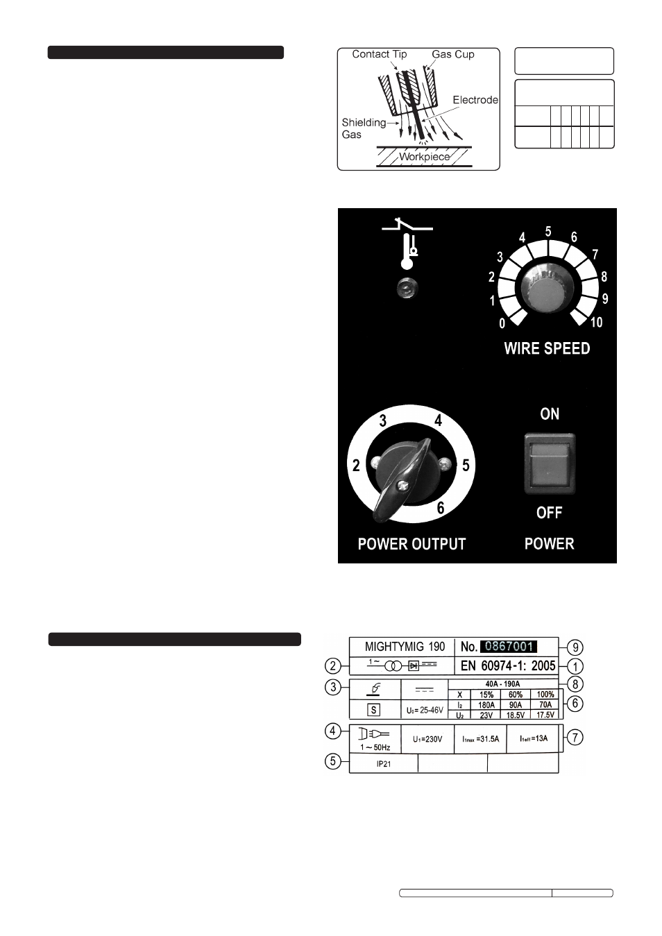
On the front of the welder is the ratings plate, giving the
following data:
1 - The standard relating to the safety and construction
of arc welding and associated equipment.
2 - Single phase transformer - rectifier.
3 - Welding with a continuous flow of welding wire.
4 - Single-phase AC supply.
5 - Rating of internal protection provided by casing.
6 - Output
U0: Rated minimum & maximum no load voltage.
I2, U2: Current and corresponding voltage.
X: Welding ratio based on a 10 minute cycle. 20% indicates 2 minutes welding and 8 minutes rest, 100% indicates continuous welding.
7 - Mains Supply U1: Rated supply voltage and frequency. Imax: Maximum current.
I1eff: Maximum effective current.
8 - Welding current range.
9 - Serial Number. Specifically identifies each welder.
5. RATINGS PLATE
Original Language Version
MIGHTYMIG170, MIGHTYMIG190, MIGHTMIG210 Issue: 2 - 26/02/10