6 . troubleshooting, Maintenance, Problem possible cause remedy – Sealey MIGHTYMIG170 User Manual
Page 7
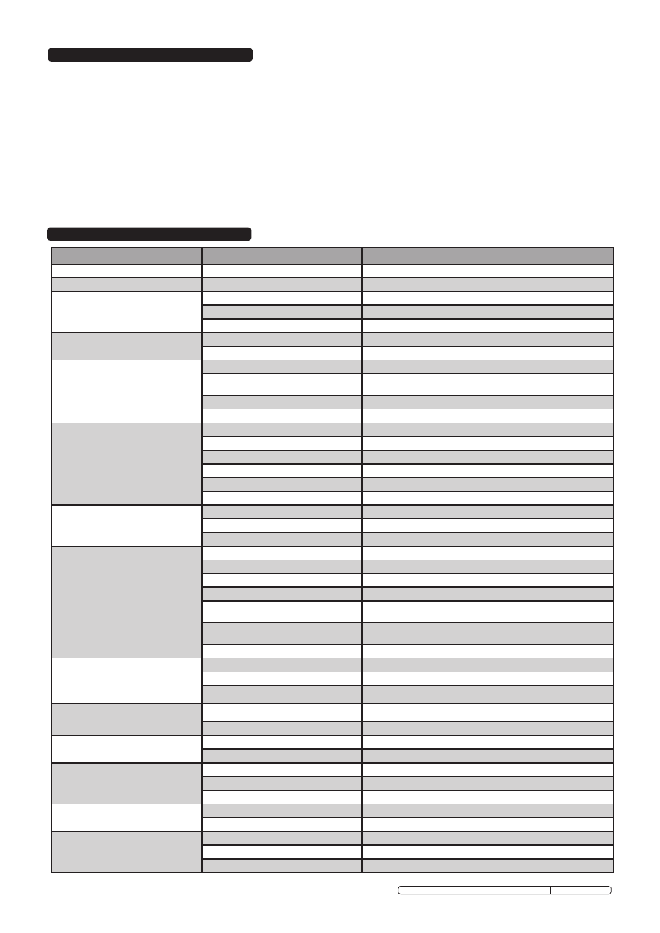
6 . TROUBLESHOOTING
PROBLEM
POSSIBLE CAUSE
REMEDY
1. Power source stops
Overheating protection activated due to overload
Protection automatically resets when transformer has cooled (about 15 min)
2. No weld current
Rectifier blown
Replace rectifier
3. No weld current
Bad connection between clamp & workpiece
Clean or grind contact surface and weld area
Break in earth lead
Repair or replace earth lead.
Break in torch lead
Repair or replace torch
4. Feed motor not working, lamp is on
Gear damaged or worn
Replace gears. (Contact service agent)
Motor defective
Replace motor (Contact service agent)
5. Wire does not feed, feed roller rotates
Pressure roller improperly adjusted
Adjust tension
dirt, copper, dust, etc, has collected in torch liner
Clean the liner from the machine forward. Use compressed air. If too much dirt,
replace the liner.
Gas cup (Nozzle) or tip defective
Replace gas cup (nozzle) and/or tip. (Section 3.9.4 to 3.9.7)
deformed wire
Check roller tension and adjust it if necessary (Section 3.10)
6. Wire feeds unevenly
dirt, etc, in liner
Clean the liner from the machine forward. Use compressed air
Gas cup (Nozzle) or Tip defective
Replace gas cup (nozzle) and/or tip. (Section 3.9.4 to 3.9.7)
Gas cup (Nozzle) spattered
Clean or replace gas cup (nozzle) (Section 3.9.4 to 3.9.7)
Feed roller groove clogged
Clean feed roller. (Section 3.12).
Feed roller groove deformed
Replace feed roller. (Section 3.12)
Pressure roller tension improper
Adjust tension. (Section 3.10)
7. Unstable arc
Incorrect settings
Check settings. (Section 4)
Impurities in weld area
Clean and/or grind workpiece. (Section 4.1.1)
Worn or defective gas cup (nozzle)
Replace gas cup (nozzle). (Section 3.9.4 to 3.9.7)
8. Porous weld
No gas
Open gas cylinder, regulate gas flow
Gas cup clogged
Clean or replace cup. (nozzle) (Section 3.9.4 to 3.9.7)
draft blowing away shielding gas
Screen off welding site or increase gas flow
Rusty or dirty joints
Clean and/or grind workpiece. (Section 4.1.1)
Torch too far from or at wrong angle to work
The distance from gas cup to workpiece should be 8 to 10mm
Gas leak
Check hoses, connections and torch assembly. (Section 3.5, 3.5). Press the gas
cup in correction position
Faulty electrovalve
Clean out or replace
9. electrode sticking in gas cup (nozzle)
Worn or defective gas cup (nozzle)
Replace gas cup (nozzle). (Section 3.9.4 to 3.9.7)
electrode deformed
Check roller tension. (Section 3.10)
Wire speed too slow
See recommendations for wire speed
10. Irregular weld head
Torch incorrectly held
Use correct torch angle
Wire weaving in weld pool
Check roller tension and adjust as needed. (Section 3.10)
11. Weld bead too narrow and raised
Weld current too low
Increase power and wire speed. (Section 4)
Weld speed too high
Move torch slower and weave a little more
12. Weld bead too wide
Weld current too high
decrease power and wire speed. (Section 4)
Weld speed too low
Move torch faster and weave less
Arc too long
Bring torch closer to workpiece
13. Poor penetration
Weld current too low
Increase power and wire speed. (Section 4)
Arc too long
Bring torch closer to workpiece
14. excessive penetration
Weld current too high
decrease power and wire speed. (Section 4)
Weld speed too slow
Move torch faster
incorrect distance of torch to workpiece
Torch distance should be 8-10mm
5.1.
WIRE FEED UNIT Check the wire feed unit at regular intervals. The feed roller wire guide plays an important part in obtaining consistent results. Poor
wire feed affects welding. Clean the rollers weekly, especially the feed roller groove, removing all dust deposits.
5.2.
TORCH Protect the torch cable assembly from mechanical wear. Clean the liner from the machine forwards by using compressed air. If the liner is
clogged it must be replaced.
5.3.
CHANGING FEED ROLLER (See Section 3.12)
5.4.
CONTACT TIP The contact tip is a consumable item and must be replaced when the hole becomes enlarged or oval. The contact tip MUST be kept free
from spatter to ensure an unimpeded flow of gas. Refer to fig.12 and section 3.9 for removal and replacement.
5.5.
GAS CUP The gas cup must also be kept clean and free from spatter. Build up of spatter inside the gas cup can cause a short circuit at the contact tip
which will result in either the fuse blowing on the printed circuit card, or expensive machine repairs. To keep the contact tip free from spatter, we
recommend the use of Sealey anti-spatter spray (MIG/722308) available from your Sealey dealer. Refer to fig.12 and section 3.9 for removal and
replacement.
5.6.
REPLACING THE LINER Wind the wire back on to the spool and secure it. Unscrew the torch from the machine and undo the brass nut. The liner should
now be visible. Pull it out and replace with a new one.
5. MAINTENANCE
Original Language Version
MIGHTYMIG170, MIGHTYMIG190, MIGHTMIG210 Issue: 2 - 26/02/10