Fig.3, Unpacking & contents 5. assembly & installation – Sealey POWERMIG6025S User Manual
Page 4
4. UNPACKING & CONTENTS
5. ASSEMBLY & INSTALLATION
4.1
UNPACKING
Due to the weight of these welders it is a four man job to unpack them
and mechanical aids are recommended. Open the carton and remove
all the accessories and other loose items of packing. We recommend
cutting away one end of the carton so that the welder can be wheeled
out of the pack directly onto a hard concrete surface. Alternatively, the
welder can be lifted out of the carton using a suitably rated lifting strap
through the lifting eyes on the top face of the welder. Unpack the wire
feed unit which can either be mounted directly onto the pivot point on
top of the welder or used at a distance from the main welder connected
via an 'umbilical cord' cable assembly.
4.2
CONTENTS
4.2.1
MAIN WELDING UNIT.
4.2.2
WIRE FEED UNIT.
Roller 0.8mm/1.0mm x 2
Roller 1.0mm/1.2mm x 2
4.2.3
TORCh & CABLE with Euro connector.
Welding Tips 0.8 x 2
Welding Tips 1.0 x 2
Welding Tips 1.2 x 2
Torch maintenance spanner
4.2.4
UMBILICAL EXTENSION CABLE ASSEMBLY
4.2.5
EARTh CLAMP CABLE
4.2.6
GAS REGULATOR
4.2.7
GAS BOTTLE RETAINING ChAIN
5.1. WELDER ASSEMBLY
5.1.1 The welder comes with wheels and handles fully assembled.
5.1.2 Decide on the positioning of the wire feed unit. If the unit is to be
mounted on the welder, do this before connecting the unit and before
placing a reel of wire into it. Lift up the wire feed unit and align the
mounting collar on its underside with the pivot pillar on top of the main
welder casing and lower it gently into position. Do not let it suddenly
drop onto the pillar.
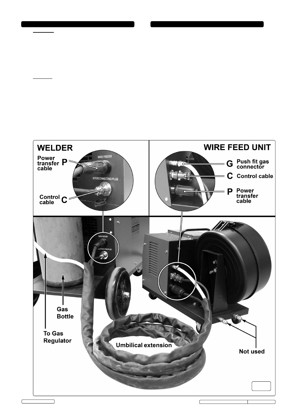
5.2. CONNECT UMBILICAL CABLE EXTENSION.
5.2.1 Whether the wire feed unit is mounted on the welder or is to be used
remotely, it must be connected to the main welder via the umbilical
cable extension provided. See fig.3 below.
5.2.2
Connect to wire feed unit. Identify the end of the umbilical cable
assembly that has the brass, push fit gas connector (G). This is the end
of the umbilical cable that connects to the back of the wire feed unit.
5.2.3 Connect the power transfer cable (P) first. Push the female quick
connector fully onto the male spigot and ensure it is fully rotated
clockwise.
5.2.4 Next, connect the control cable (C) to the threaded connector. Insert the
plug and rotate it until it engages with the keyway inside the socket.
Engage the threaded collar with the socket thread and screw it onto the
socket body, thus pulling the plug into full engagement.
5.2.5 Now connect the gas pipe (G). Push the brass fitting on the end of the
gas pipe into the brass socket until it clicks into place.
Original Language Version
© Jack Sealey Limited
fig.3
POWERMIG6025S, POWERMIG6035S Issue: 2(L) -06/03/14