Maintenance – Sealey POWERMIG6025S User Manual
Page 9
9.4
COMMENCING WELDING.
9.4.1
Before carrying out difficult sections of welding, tests should be
carried out on scrap pieces of metal. These tests should be carried
out to find the best control settings in order to obtain the best welding
result. As a starting point refer to the welding guide below. If the arc
melts in drops and tends to go out, the speed of the wire should be
increased or the welding current decreased. If, however, the wire hits
the piece violently and causes material to be projected, the wire
speed should be reduced.
9.4.2
It should be remembered that in order to obtain the best results, each
type of wire is suited to a specific current and wire feed speed.
Therefore, for difficult sections of welding and welding which requires
a great deal of time, wires with different diameters should be tried so
that the most suitable may be chosen.
9.4.3
Turn on and adjust the protective gas using the pressure regulator.
Adjust to a flow rate of 5-7 l/min.
9.4.4 NOTE: At the end of the job, remember to turn off the protective gas.
9.4.5
Switch the welder on and set the welding current by means of
the rotary switches and by referring to the welding reference table
above.
9.4.6
Ensure that the earth clamp is in contact with the workpiece.
9.4.7
Press the torch button, keeping the torch at a safe distance from the
workpiece.
9.5
Aluminium Welding.
Argon or an Argon-Helium mixture should be used for shielding. The
wire used must have the same characteristics as the material to be
welded. Always use an alloy wire (i.e. aluminium/silicium);
DO NOT
use pure aluminium wire. A problem you may experience when
aluminium MIG welding is in pulling the wire for the whole length of
the torch, as aluminium has poor mechanical characteristics. The
smaller the diameter of wire the more difficult the wire feed may be.
To overcome this problem do the following.
- Use contact tip suitable for aluminium.
- Replace the wire puller rollers with aluminium compatible rollers.
- Replace the steel guide hose for wire feed with a Teflon guide hose.
- For information contact your local Sealey dealer .
10. MAINTENANCE
WARNING! Ensure the unit is disconnected from the mains
power supply before performing any maintenance or service.
10.1
Regularly check all welding cables and secondary terminals to ensure
they are in good order and connected correctly, also check during
welding to ensure they are not overheating.
10.2
Check that the gas hose connections are tight and that there are no
gas leaks.
10.3
Wire feed unit.
Check the wire feed unit at regular intervals. The feed roller wire guide
plays an important part in obtaining consistent results. Poor wire
feeding affects welding. Clean the rollers weekly, especially the feed
roller groove, removing all dust deposits from the feeder area.
10.4
Changing Feed Roller / Rollers IMPORTANT: Set up the feed rollers
according to the wire size required for the job in hand. Refer to section 6.
Original Language Version
© Jack Sealey Limited
10.5 Torch
Protect torch cable assembly from mechanical wear. Also do not allow
the torch or its cable to come into contact with hot surfaces, especially
a hot workpiece as this would cause the insulating materials to melt,
making the torch unsafe and unusable.
- Make regular checks on the gas pipe and connector seals;
- Every time the wire reel is changed, blow out the wire-guide hose
using dry compressed air (max. 5 bar) to make sure it is not damaged;
- Before using the welding machine, always check the torch terminal
parts for wear and make sure they are assembled correctly: nozzle,
contact pipe, gas diffuser.
10.6
Contact Tip (to remove the tip refer to section 6.7 and fig.16).
The contact tip is a consumable item and must be replaced when the
hole becomes enlarged or oval. The contact tip
MUsT be kept free
from spatter to ensure an unimpeded flow of gas.
10.7
Gas Cup (to remove the tip refer to section 6.7 and fig.16).
The gas cup must also be kept clean and free from spatter. Build up
of spatter inside the gas cup can cause a short circuit at the contact
tip which will result in either the fuse blowing on the printed circuit
card, or expensive machine repairs. To keep the contact tip free from
spatter, we recommend the use of Sealey anti-spatter spray
(MIG/722308) available from your Sealey Dealer.
10.8
Changing Fuses
The fuses are located on the back panel of the main welding unit and
are mainly blown for the following reasons:
Spatter collecting in the gas cup, causing contact tip to short circuit.
Wire tension is too great. A sudden surge of current.
10.9
INTERNAL MAINTENANCE / INSPECTION
INTERNAL INSPECTION AND MAINTENANCE OPERATIONS
SHOULD BE CARRIED OUT ONLY AND EXCLUSIVLY BY SKILLED
OR AUTHORISED ELECTRICAL/MECHANICAL TECHNICIANS.
WARNING BEFORE REMOVING THE WELDING MACHINE PANELS
AND WORKING INSIDE THE MACHINE MAKE SURE THE
WELDING MACHINE IS SWITCHED OFF AND DISCONNECTED
FROM THE MAIN POWER SUPPLY OUTLET.
If checks are made inside the welding machine while it is live, this
may cause serious electric shock due to direct contact with live parts
and/or injury due to direct contact with moving parts.
- Inspect the welding machine regularly, with a frequency depending
on use and the dustiness of the environment, and remove the dust
deposited on the transformer, reactance and rectifier using a jet of dry
compressed air (max. 10 bar).
- Do not direct the jet of compressed air on the electronic boards;
these can be cleaned with a very soft brush or suitable solvents.
- At the same time make sure the electrical connections are tight and
check the wiring for damage to the insulation.
- At the end of these operations re-assemble the panels of the welding
machine and screw the fastening screws right down.
- Never, ever carry out welding operations while the welding machine
is open.
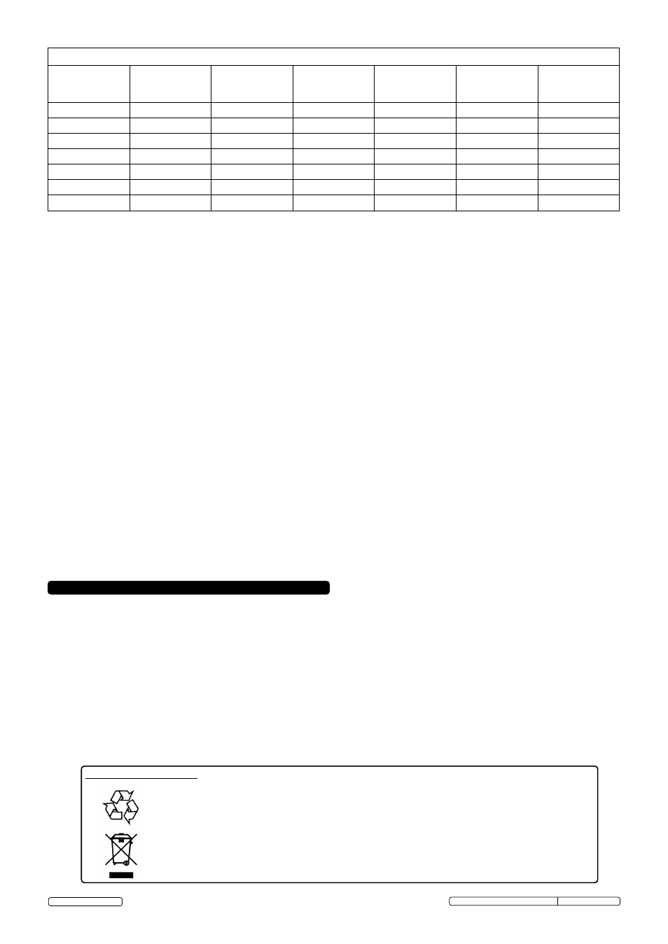
WELDING REFERENCE TABLE (for general guidance only)
Material
Thickness
(mm)
Wire
Diameter
(mm)
Liner Inner
Diameter
(mm)
Liner
Specification
(mm)
Current
(Amps)
Voltage
(Volts)
Gas Flow
(l/min)
0.8 to 1.5
Ш0.8
Ш1.4
1.2 x 1.6 (blue)
50 to 90
17 to 18
6
1.0 to 2.5
Ш0.8
Ш1.4
1.2 x 1.6 (blue)
60 to 100
18 to 19
7
2.5 to 4.0
Ш0.8
Ш1.4
1.2 x 1.6 (blue)
100 to 140
21 to 24
8
2.0 to 5.0
Ш1.0
Ш1.6
1.2 x 1.8 (black)
70 to 120
19 to 21
9
5.0 to 10
Ш1.0
Ш1.6
1.2 x 1.8 (black)
120 to 170
23 to 26
10
5.0 to 8.0
Ш1.2
Ш1.6
1.2 x 1.8 (black)
110 to 180
22 to 24
10
8.0 to 12
Ш1.2
Ш1.6
1.2 x 1.8 (black)
160 to 300
25 to 38
12
Environmental Protection.
Recycle unwanted materials instead of disposing of them as waste. All tools, accessories and packaging
should be sorted, taken to a recycle centre and disposed of in a manner which is compatible with the
environment.
WEEE REGULATIONS. Dispose of this product at the end of its working life in compliance with the EU
Directive on Waste Electrical and Electronic Equipment. When the product is no longer required, it must be
disposed of in an environmentally protective way.
POWERMIG6025S, POWERMIG6035S Issue: 2(L) -06/03/14