Fig.12, 6 . setting up the wire feed – Sealey POWERMIG6025S User Manual
Page 6
6.1 The wire feed mechanism has two separate grooved drive rollers and
two separate pressure rollers. The pressure rollers are in separate
housings which are held in place and acted upon by a single, central
pressure adjustment knob as shown in fig.11 above. To access the
drive mechanism pull the pressure adjustment knob forwards and
allow it to hinge downwards. As you do so the pressure roller housings
will spring upwards as shown in fig.12 below.
6.5
Straighten about 50-100mm of spool wire (do not allow wire to uncoil).
Ensure that the wire is undistorted and clean cut with no burrs or sharp
points. (Note: Burrs or sharp points at wire tip may damage the torch
liner.) Gently push the wire through the flexible wire guide (see fig.9)
until it emerges into the wire feed drive unit. Guide the wire over the first
roller and through the central guide tube. Guide the wire over the
second roller and into the torch fitting wire guide by 50 to 100mm.
6.6 Close and hold down each pressure roller housing then hinge the
pressure knob upwards and onto the housings until it snaps into
position. Set an intermediate pressure between marks 2 and 3. Turning
the knob clockwise increases the pressure. Turning the knob
anti-clockwise decreases the pressure. (See fig.15).
6.2
The wire drive unit is supplied with two pairs of rollers. One pair has
drive grooves for Ø0.8mm and Ø1.0mm wire. The second pair has
drive grooves for Ø1.0mm and Ø1.2mm.
Note that it is essential to place the required rollers the right way
round on the drive mechanism.
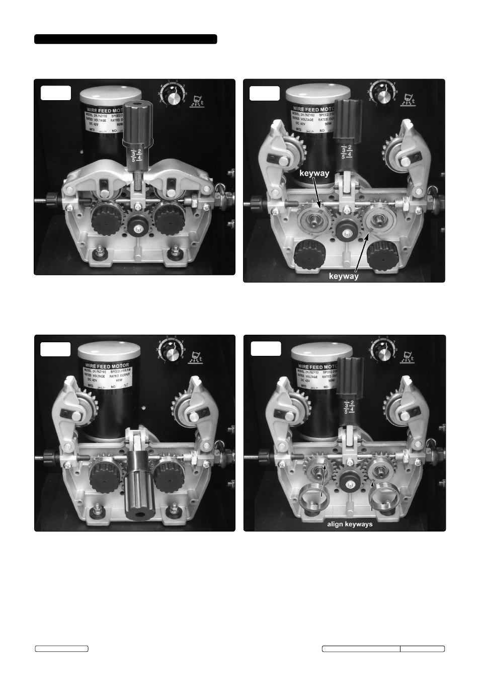
6.3
The roller groove size is stamped on the face of each roller adjacent
to the appropriate groove. Ensure that the groove size you require is
positioned next to the drive gear so that it will be in line with the wire
feed path. To reverse the position of the rollers firstly unscrew and
remove the knurled knobs that hold each roller in position (see fig.13).
Note that there is a keyway in each roller which must align with the
keyway on the drive mechanism and the two components are held
together with a close fitting square key (see fig.13). Once the knobs
are removed the rollers can be pulled off the geared drive wheels. If
possible, try not to dislodge the square keys from the keyways.
fig.12
MAKE SURE ThAT ThE WIRE FEED ROLLERS, ThE WIRE GUIDE hOSE
AND ThE CONTACT TIP OF ThE TORCh MATCh ThE DIAMETER AND
TYPE OF WIRE TO BE USED AND ARE FITTED CORRECTLY.
6.4.1 Before placing the rollers back onto the drive mechanism, rotate them
until the keyway in each roller aligns with the key/keyway in the geared
drive and then slide them into position. See fig.14 below.
6.4.2 Double check that both rollers are correctly positioned to present the
same groove size to the drive path. Fix rollers in position by screwing
into place the knurled knobs previously removed.
6.4 The rollers can now either be removed, reversed and refixed or replaced
with the other pair. In either instance the required drive grooves must be
furthest away from you at the back of the roller in order to align with the
wire drive path.
Original Language Version
© Jack Sealey Limited
fig.11
fig.13
fig.14
6 . SETTING UP ThE WIRE FEED
POWERMIG6025S, POWERMIG6035S Issue: 2(L) -06/03/14