Fig.22 – Sealey POWERMIG6025S User Manual
Page 8
IMPORTANT.
Should you have no welding experience, we recommend you seek
training from an expert source to ensure your personal health & safety.
You must familiarise yourself with welding applications and limitations,
and specific potential hazards peculiar to welding. Good Mig welding
may be achieved only with continued, supervised practice.
9.1
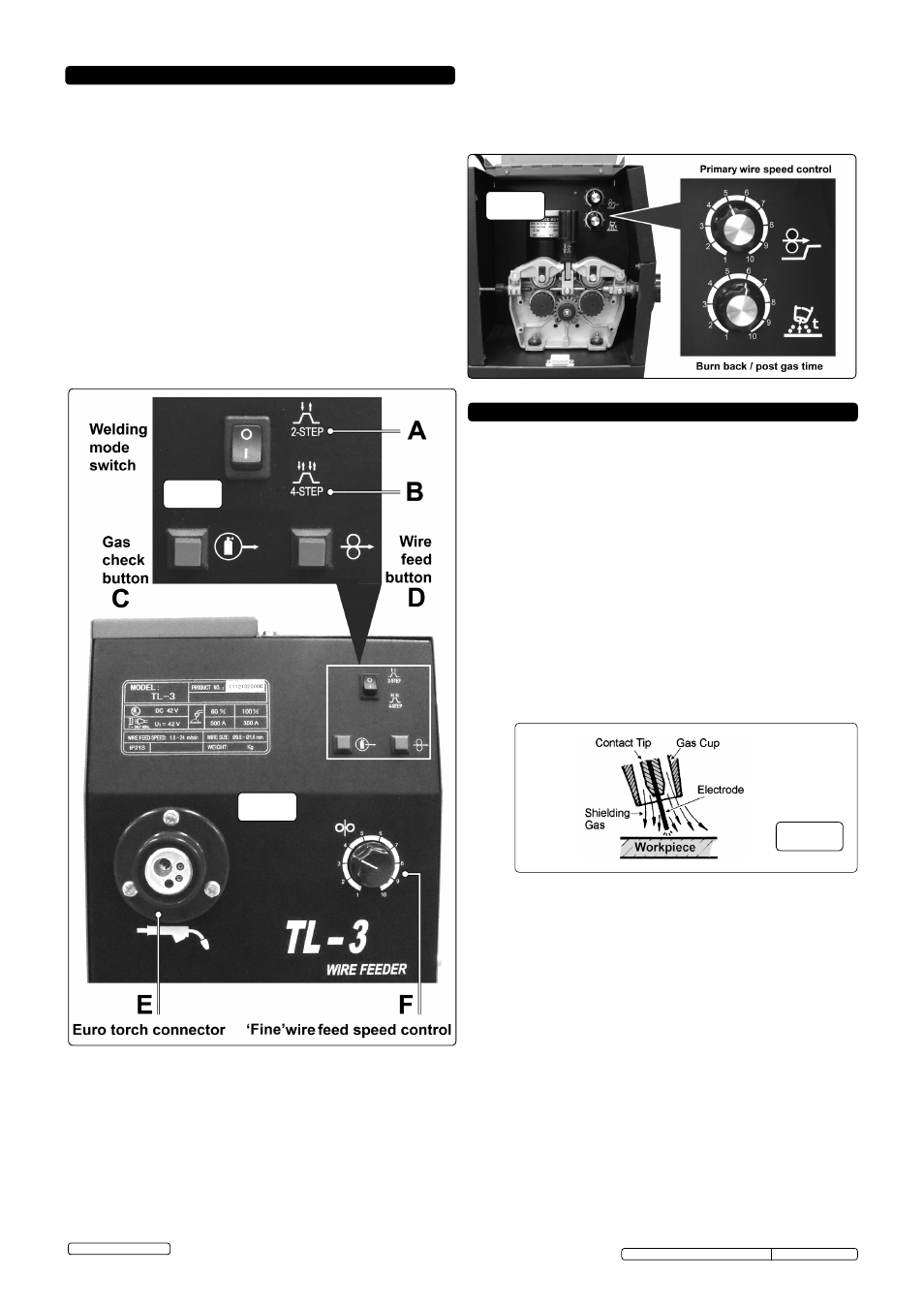
Mig/Mag welding. (See fig.22 ). A spool of welding wire is placed on
the spool holder and automatically fed through an insulated liner in the
torch to its tip. The torch consist of a switch, liner, gas hose, and
control cable. The switch activates the wire feed roller and the gas
flow. Releasing the switch stops wire feed and gas flow. The weld
current is transferred to the electrode (the wire) from the contact tip at
the torch end.
Wire speed must be adjusted according to power output. The higher
the current the faster the wire speed. A gas cup fits over the contact
tip to direct gas flow towards the weld ensuring the arc welding
process is shielded from oxidising air contamination (fig.22). The
shielding gas also assists heating of the weld. The torch is connected
to the positive side of a DC rectifier, and negative clamp is attached to
the workpiece.
9. WELDING PRINCIPLES
8 . REMOTE WIRE DRIVE UNIT CONTROLS
fig.22
Original Language Version
© Jack Sealey Limited
fig.19
fig.20
fig.21
8.1
WELDING MODE SWITCh (TORCh OPERATION)
8.1.1
2-Step Welding Mode (fig.19A) In 2-step welding mode the torch
operates in the normal way. When the torch trigger is pressed and
held, both the wire and the gas are continuously supplied. When the
trigger is released, the flow of gas and wire ceases.
8.1.2
4-Step Welding Mode (fig.19B) In 4-step welding mode, long welds
can be executed without having to continuously hold down the torch
trigger. To activate this mode, press and release the torch trigger to
initiate the continuous supply of both the wire and the gas. At the end
of the weld, press and release the trigger again to cut off the supply of
wire and gas.
8.1.3
Gas Check Button (fig.19C) When working remotely from the main
welding unit, prior to commencing welding, the Gas Check Button can
be used to check that gas is flowing to the torch. Briefly hold down the
button and listen for the hiss of gas at the torch tip. Release the button
as soon as gas is heard. If no gas is heard to flow, check that the
bottle valve and/or regulator are open.
8.1.4
Wire Feed Button (fig.19D) Similarly, when working remotely from the
main welding unit, prior to commencing welding, the Wire Feed Button
can be used to check that the wire feed unit is powered and wire is
being fed to the torch. Hold down the button and listen for the action of
the wire feed unit and/or observe the wire issuing from the torch tip.
8.3
BURN BACK / POST GAS TIME
8.3.1
The burn back/post gas time control allows a small amount of wire and
gas to be fed to the weld, even after the torch trigger has been
released. This rotary control is situated inside the wire feed
compartment below the primary wire speed control. See fig.21 below.
8.1.5
Euro Torch Connector (fig.20E) The torch should already be
connected as described in Section 5.4. Ensure that the locking
nut/ring is fully tightened and the wire has been fed through to the
torch as described in Section 6.7.
8.2
WIRE FEED CONTROLS
8.2.1
The wire feed speed can be set using a combination of the Primary
Wire Speed Control situated in the wire feed compartment and the
'Fine' Wire Feed Speed Control on the Wire feed unit front panel.
8.2.2
Primary wire feed control (fig.21) Use this rotary control to set the
basic wire feed speed required by the welding parameters of the weld
to be executed.
8.2.3
'Fine' wire feed speed control (fig.20F) If during the course of
welding, fine adjustment is needed to the wire speed, use this rotary
control which is readily accessible on front panel of wire feed unit.
9.2
Preparation for welding.
IMPORTANT:
BEFORE YOU COMMENCE, MAKE SURE THE
MACHINE IS SWITCHED OFF AT THE MAINS. IF WELDING A
VEHICLE, DISCONNECT THE BATTERY OR FIT AN ELECTRONIC
CIRCUIT PROTECTOR. ENSURE YOU READ AND UNDERSTAND
THE SAFETY INSTRUCTIONS IN CHAPTER 1.
9.2.1
Connecting the Earth Lead.
Connect the earth lead as described in section 5.5.
To ensure a complete circuit, the earth lead clamp must be securely
attached to the workpiece that is to be welded.
a) Best connection is obtained by grinding the point of contact on the
workpiece before connecting clamp to the workpiece.
b) The weld area must also be free of paint, rust, grease, etc.
c) If welding a vehicle, disconnect vehicle battery or fit an “Electronic
Circuit Protector” to battery, (available from your Sealey dealer).
9.2.2
The wire feed rate rotary controls are used to set the speed of the wire
feed. In principle, the lower the amperage number the slower the wire
speed.
9.3
Gas types and their use.
Welding mild steel with CO² gas is appropriate for most welding tasks
where spatter and high build up of weld do not pose a problem. To
achieve a spatter free and flat weld however, as a guideline, use an
Argon/CO² mixture. To weld aluminium use: Argon gas or Argo-
Helium mixture, 0.8mm Contact Tip, 0.8mm Aluminium Wire,
(MIG/2/KAL08)
Liner (red) Aluminium.
POWERMIG6025S, POWERMIG6035S Issue: 2(L) -06/03/14