Rose Electronics CrystalView DVI Fiber User Manual
Page 17
CRYSTALVIEW DVI FIBER INSTALLATION AND OPERATIONS MANUAL
13
Carefully remove the four (4) Phillips screws from the bottom of the unit. If
your model is a dual version, also remove the UNC screws that secure the
video connectors.
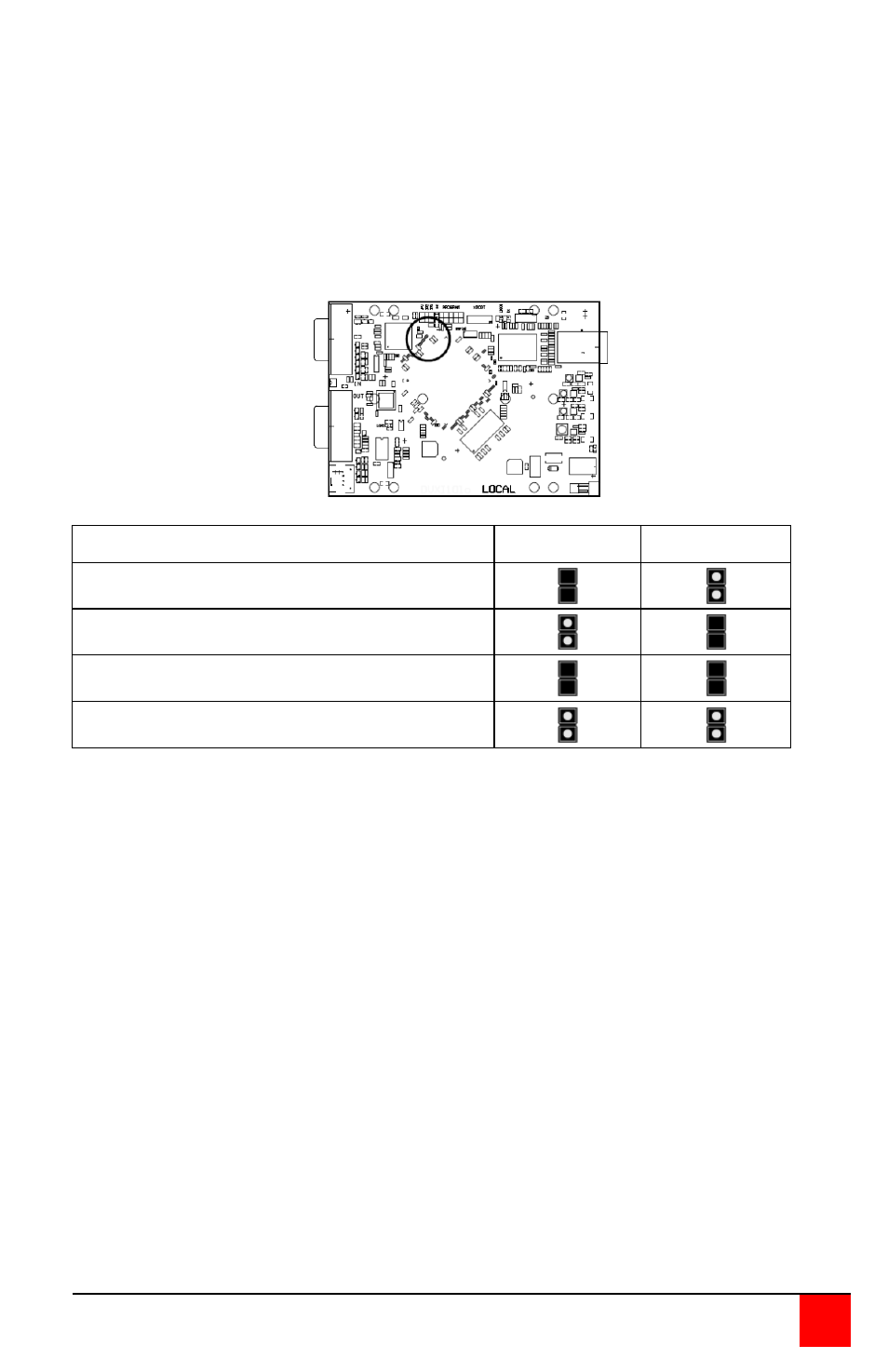
A- Remove the top cover exposing the internal PC board as shown
below
B- Locate jumpers JP1 and JP2.
C- Place a jumper block on the appropriate jumpers as shown in the
table below:
DDC Source
JP1 setting
JP2 setting
From internal table (default)
From local monitor
From remote monitor (see procedure)
Reset to default values
Load DDC information from the Remote monitor and save to the internal
DDC table
To load the DDC information from the remote monitor, perform the following
steps to properly load the DDC information from the remote monitor to the
local unit.
1. Switch off the power on the local and remote units and disconnect the
video cable to the remote monitor(s).
2. Open the LOCAL unit exposing the internal PC board
3. Locate the jumper block on terminal JP3. Remove the jumper block
from JP3 and place it on jumper JP2. Note the position of the jumper
block on JP3. It will be replaced when the DDC load procedure
completes. JP1 and JP2 should now have a jumper on them.
(NOTE: Perform this procedure on both PC boards on the dual
models)
4. Make sure the interconnect CAT5 cable is connected and turn on the
local and remote units.
FIBER Connector