Instruction for mounting – Solare Datensysteme Solar-Log Sensor basic User Manual
Page 7
7
Instruction for Mounting
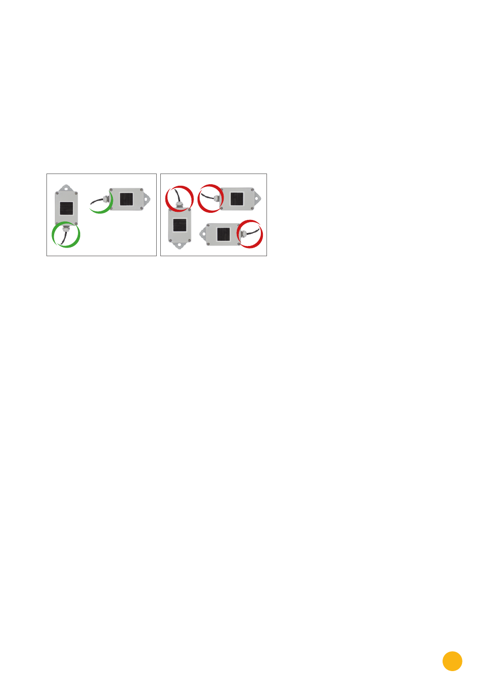
Install the irradiance sensor with the same orientation and declination as the PV generator, most suitable in
the plane with the pv generator. Choose an unshaded location for the irradiance sensor. To prevent snow
on the sensor choose a location sidewise or above, but not below the PV generator. Usually an overlapped
mounting trace of the PV generator can be used for mechanical installation of the irradiance sensor. Other-
wise use another suitable assembling aid for mechanical installation of the sensor.
Recommended Mounting
Not allowed
Terminal block connector
Solar-Log™
Sensor Basic Cable
1 (Data+)
Brown: Data+
2 (+12 V)
Red: +12 Vdc (Vcc)
3 (GND)
Black: 0 V (GND)
4 (Data-)
Orange: Data-
Attention!
Opening the sensor
is not necessary for installing
the sensor. Opening the sensor
will void your warranty!
Cabling for the data line to the Solar-Log™
Attention!
Interchanging the connection
cables may result in damage to sensor.
•
The connection cable is 4-wire and includes
the 12 V power supply and the data line to the
Solar-Log™.
•
No separate power supply is required.
•
The connection cable can be extended (up to
50 m).
•
However, a 8 V supply voltage must be provided
at the end of the cable.
•
The cable must also be suitably protected in
outside areas. The cabling in inside areas can
consist of a shielded data cable.
•
The Sensor Basic is connected to a RS485
interface
•
parallel to the inverter bus (min. Firmware 2.5) or
to an unused RS485 interface on the Solar-Log™
•
The cable shielding must have an equipotential
bond.
•
The four wires in the connection cable must be
joined
•
to the 4-pin connector of the Solar-Log™. The
wire assignments are printed on the back of the
sensor and are made as follows:
Startup
•
When the Solar-Log™ is switched on, the Sensor
Basic is also powered up automatically.
•
The Sensor Basic must then be configured on the
desired RS485 interface:
1. Use the web interface to access the Solar-Log™
configuration menu.
2. Select “M&T Sensor” for the inverter selection
in the Configuration | Devices | Definition
menu.
3. Carry out the inverter detection. The Sensor
Basic is integrated with the system in the same
way as an inverter.