Thermo Pride C Premiere Series User Manual
Page 10
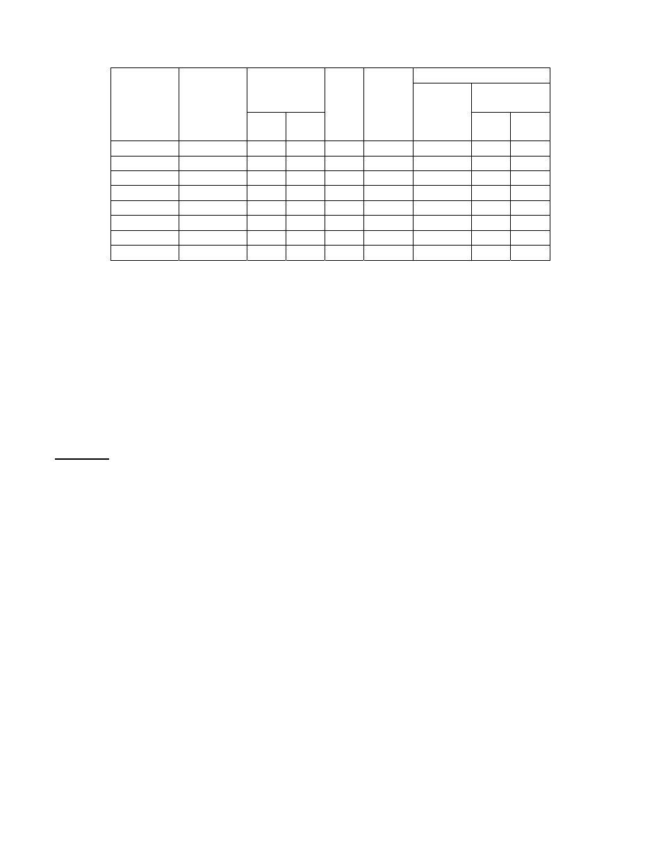
FUSE SIZING - TABLE A
Recommendations
Compressor
Fuse or HACR
Circuit Breaker
Unit Model
Voltage/
Phase/ Hertz
3
4
Fan
Motor
FLA
5
Minimum
Circuit
RLA LRA
Ampacity
AMPS
Min.
Copper
Wire Size*
(AWG)
Min.
2
AMPS
Max.
AMPS
AC14241E2 208-230/1/60 13.5 58.3 0.8
18
#12
20
25
AC14301E2 208-230/1/60 12.8
64
0.8
17
#12
20
25
AC14361E2 208-230/1/60 14.1
77
0.8
19
#12
20
25
AC14421E2 208-230/1/60 17.9 112
0.8
24
#10
25
30
AC14481E2 208-230/1/60 19.9 109
1.6
26
#10
30
35
AC14601E2 208-230/1/60 26.4 134
2.1
36
#8
35
40
AC14483E2 208-230/3/60 13.1 83.1 1.6
18
#12
20
25
AC14603E2 208-230/3/60 16 110 2.1
23
#10
25
30
NOTE: Recommended wire sizes are for copper conductors only.
*Use (as minimum) type "T" or "TW" wire. 60 C.
Local and/or national electrical codes dictate which wire size you must use!
For
example:
1
If a 25 or 30 amp fuse is used, a minimum wire size of 10 AWG must accompany it.
2
If you fuse to maximum sizes, your wire size must be adjusted accordingly.
3
R.L.A.=Compressor running load amps.
4
L.R.A.=Compressor locked rotor amps.
5
F
.L.A.=Full load amps of condenser blower motors.
In the event a fuse blows, investigate for the cause. Do not put in a larger fuse and do not exceed maximum
fuse size listed on name plate. The name plate is located just above the valve connection on the outside
surface of the outdoor unit.
NOTICE: Before the Air Conditioner unit is started, the following points must be checked by the installer
and/or electrician.
1). Check every electrical connection of "PUSH-ON" or "SCREW-ON" type terminals to insure it is secured
tightly on its proper post.
2). Review wiring diagram for proper routing.
3). All wiring must comply with NEC or local codes for wire sizes. Also, it is suggested that the next larger
size wire to be used when long runs in excess of 100 ft. are experienced. Reference the following wiring
diagrams when wiring or servicing.
A loose terminal will cause poor flow of electrical power to the compressor and result in very high current
draw. This can lead to blown fuses, burned wires, burned contact points and a premature compressor failure.
Each electrical contact has been factory checked, however, connections may loosen up due to vibration in
transit. Please be certain that all electrical connections are tight.
10