Notice – Thermo Pride LX-13 User Manual
Page 7
SECTION VIII: ELECTRICAL
CONNECTIONS
GENERAL INFORMATION & GROUNDING
Check the electrical supply to be sure that it meets the values specified
on the unit nameplate and wiring label.
Power wiring, control (low voltage) wiring, disconnect switches and over
current protection must be supplied by the installer. Wire size should be
sized per NEC requirements.
The complete connection diagram and schematic wiring label is located
on the inside surface of the unit service access panel.
FIELD CONNECTIONS POWER WIRING
1. Install the proper size weatherproof disconnect switch outdoors and
within sight of the unit.
2. Remove the screws from the control box cover and remove from
unit.
3. Run power wiring from the disconnect switch to the unit.
4. Route wires from disconnect through power wiring opening provided
and into the unit control box as shown in Figures 6 or 7.
5. Install the proper size time-delay fuses or circuit breaker, and make
the power supply connections.
FIELD CONNECTIONS CONTROL WIRING
1. Route low voltage wiring into bottom of control box as shown in Fig-
ures 6 or 7. Make low voltage wiring connections inside the low volt-
age box per Figures 8-9.
2. The complete connection diagram and schematic wiring label is
located on the inside surface of the unit service access panel.
3. Replace the control box cover removed in Step 2.
4. All field wiring to be in accordance with national electrical codes
(NEC) and/or local-city codes.
5. Mount the thermostat about 5 ft. above the floor, where it will be
exposed to normal room air circulation. Do not place it on an outside
wall or where it is exposed to the radiant effect from exposed glass
or appliances, drafts from outside doors or supply air grilles.
6. Route the 24-volt control wiring (NEC Class 2) from the outdoor unit
to the indoor unit and thermostat.
Refrigerant charging should only be carried out by a qualified air con-
ditioning contractor.
Compressor damage will occur if system is improperly charged. On
new system installations, charge system per tabular data sheet for
the matched coil and follow guidelines in this instruction.
IT IS UNLAWFUL TO KNOWINGLY VENT, RELEASE OR DIS-
CHARGE REFRIGERANT INTO THE OPEN AIR DURING REPAIR,
SERVICE, MAINTENANCE OR THE FINAL DISPOSAL OF THIS
UNIT.
All field wiring must USE COPPER CONDUCTORS ONLY and be in
accordance with Local, National, Fire, Safety & Electrical Codes. This
unit must be grounded with a separate ground wire in accordance
with the above codes.
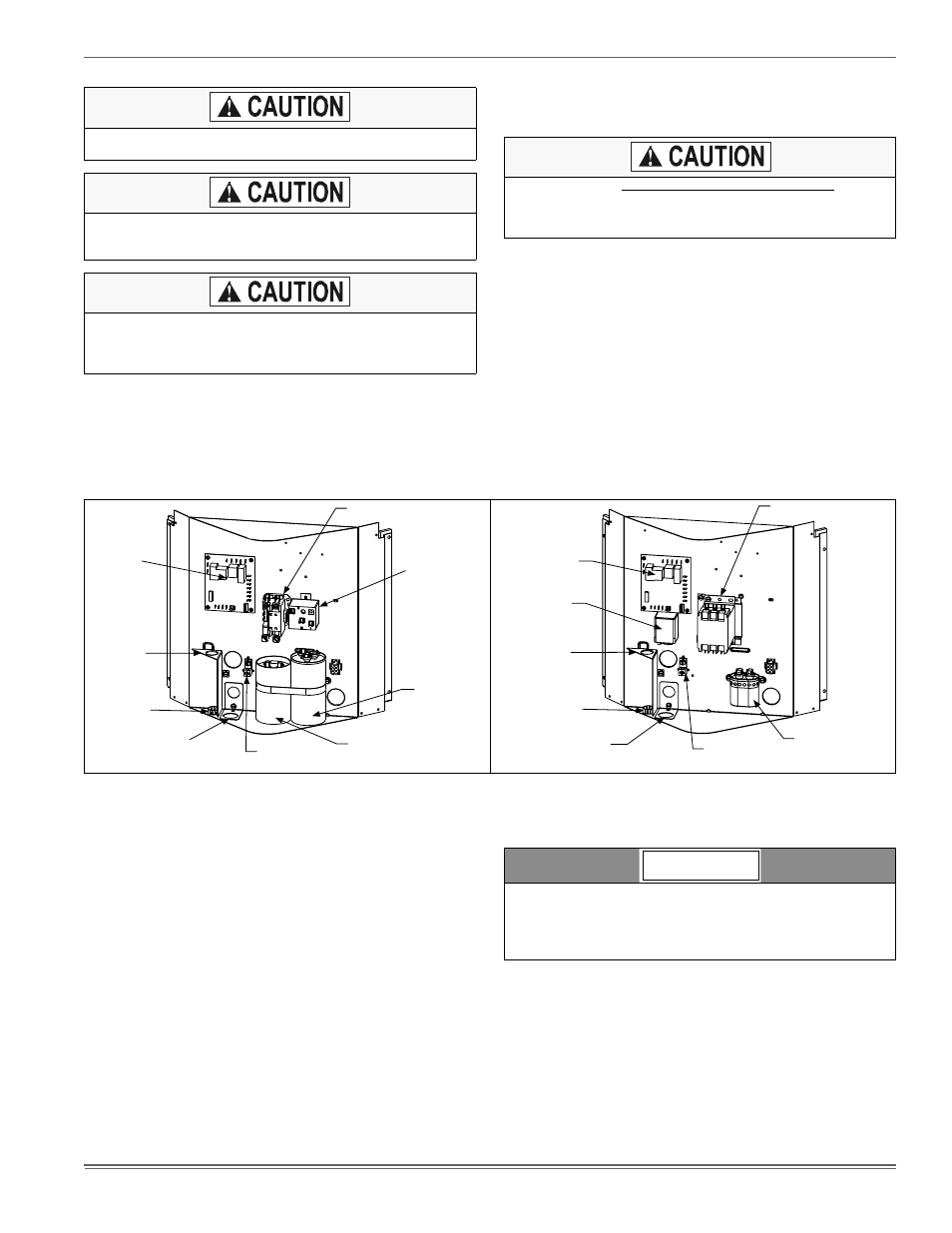
FIGURE 6:
Outdoor Unit Control Box - Single Phase
FIGURE 7:
Outdoor Unit Control Box - Three Phase
Start
Relay
(Optional)
Defrost
Control
Board
Start Capacitor
(Optional)
Ground
Lug
“Fingered”
Bushing
Low
Voltage
Box
Reversible High
Voltage Conduit Plate
Contactor
Dual
Run/Fan
Capacitor
Fan
Relay
Defrost
Control
Board
Ground
Lug
“Fingered”
Bushing
Low
Voltage
Box
Reversible High
Voltage Conduit Plate
Contactor
Fan
Capacitor
To eliminate erratic operation, seal the hole in the wall at the thermo-
stat with permagum or equivalent to prevent air drafts affecting the
operation of in the thermostat.
A Start Assist Kit is available and recommended for long line set
applications or in areas of known low voltage problems.
NOTICE
7