Thermo Pride LX-13 User Manual
Page 9
9
SECTION IX: SYSTEM START-UP
ENERGIZE CRANKCASE HEATER
If this unit is equipped with a crankcase heater for the compressor, a
warning label with an adhesive back is supplied in the unit installation
instruction packet. This label should be attached to the field supplied
disconnect switch where it will be easily seen.
In order to energize the crankcase heater, set the indoor cooling ther-
mostat to the OFF position. Close the line power disconnect to the unit.
WITH POWER TO UNIT AND THERMOSTAT IN COOLING
POSITION:
1. In the cooling cycle, discharge gas is pumped to the outdoor coil
which is the condenser. The indoor coil is the evaporator.
2. If fan switch is in ON position, a circuit is made through blower relay
to provide continuous blower operation.
3. With fan switch in AUTO position, a circuit is made from thermostat
cooling contact through blower relay to provide blower operation.
4. System will cycle with thermostat demand to provide cooling as
needed.
An attempt to start the compressor without at least 8 hours of crank-
case heat will damage the compressor.
TABLE 1:
R-410A Saturation Properties
Temp °F
Pressure
PSIG
Temp °F
Pressure
PSIG
Temp °F
Pressure
PSIG
Temp °F
Pressure
PSIG
Temp °F
Pressure
PSIG
45
130
60
170
75
217
90
274
105
341
46
132
61
173
76
221
91
278
106
345
47
135
62
176
77
224
92
282
107
350
48
137
63
179
78
228
93
287
108
355
49
140
64
182
79
232
94
291
109
360
50
142
65
185
80
235
95
295
110
365
51
145
66
188
81
239
96
299
111
370
52
147
67
191
82
243
97
304
112
375
53
150
68
194
83
247
98
308
113
380
54
153
69
197
84
250
99
313
114
385
55
156
70
201
85
254
100
317
115
391
56
158
71
204
86
258
101
322
116
396
57
161
72
207
87
262
102
326.
117
401
58
164
73
211
88
266
103
331
118
407
59
167
74
214
89
270
104
336
119
412
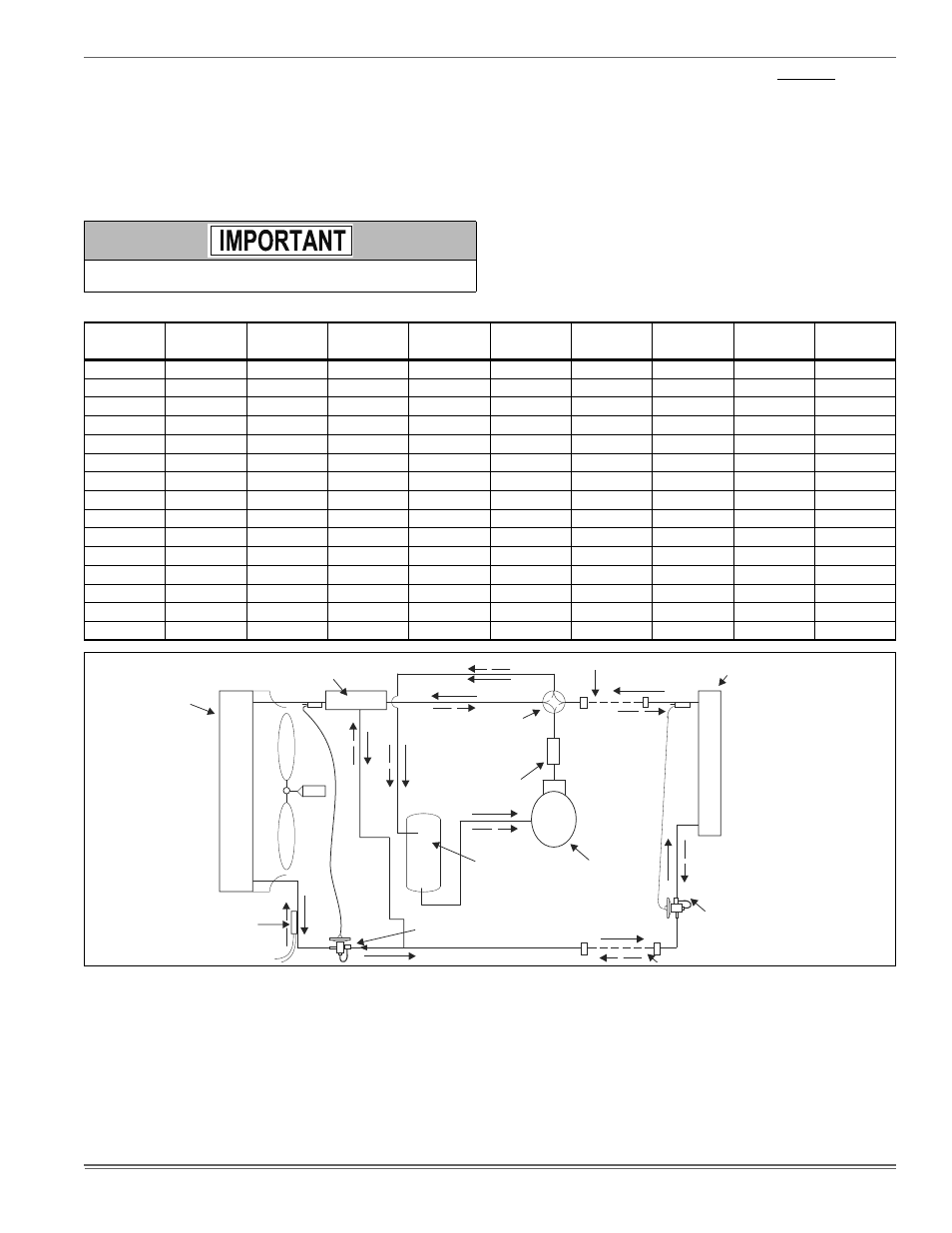
FIGURE 10:
Heat Pump Flow Diagram
CHARGE COMPENSATOR
(Empty in cooling / full in heating)
(Not included in all Units)
FIELD CONNECTED LINE
INDOOR COIL
OUTDOOR
COIL
4-WAY
REVERSING
VALVE
FILTER DRYER
(Solid core)
SUCTION
ACCUMULATOR
LIQUID
SENSOR
COMPRESSOR
BI-FLOW
TXV/CHECK
VALVE (Cooling) **
BI-FLOW
TXV/CHECK
VALVE OR ORIFICE (Heating)