8dehumidification control, Cfm selection board settings – Thermo Pride LX-13 User Manual
Page 8
8
DEHUMIDIFICATION CONTROL
A dehumidification control accessory 2HU06700124 may be used with
variable speed air handlers or furnaces in high humidity areas. This
control works with the variable speed indoor unit to provide cooling at a
reduced air flow, lowering evaporator temperature and increasing latent
capacity. The humidistat in this control opens the humidistat contacts on
humidity rise. To install, refer to instructions packaged with the acces-
sory. Prior to the installation of the dehumidification control, the jumper
across the HUMIDISTAT terminals on the indoor variable speed air han-
dler or furnace CFM selection board must be removed.
During cooling, if the relative humidity in the space is higher than the
desired set point of the dehumidification control, the variable speed
blower motor will operate at lower speed until the dehumidification con-
trol is satisfied. A 40-60% relative humidity level is recommended to
achieve optimum comfort.
If a dehumidification control is installed, it is recommended that a mini-
mum air flow of 325 cfm/ton be supplied at all times.
For connection diagrams for all UPG equipment refer to “Low Voltage
System Wiring” document available online at www.upgnet.com in the
Product Catalog Section.
CFM SELECTION BOARD SETTINGS
For proper system operation the CFM Selection control jumpers must
be set properly.
Refer to the Tabular Data Sheet for the recommended air flow settings
for each size condensing unit.
Set the cooling speed per the instructions for the air handler or furnace
by selecting the correct COOL and ADJ taps. Verify the airflow using
the LED display on the CFM selection board.
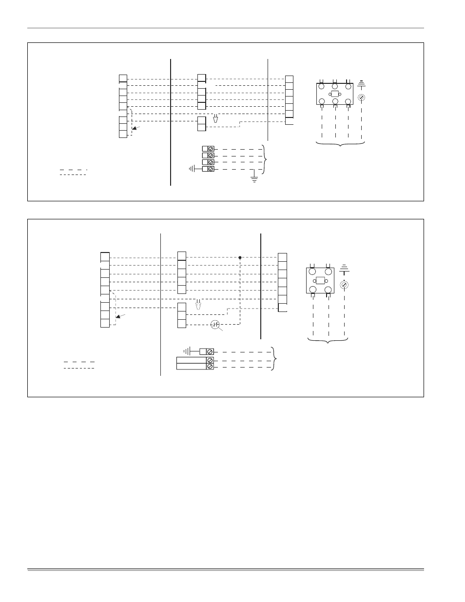
FIGURE 8:
Typical Field Wiring (Air Handler / Electrical Heat) - (Three Phase)
FIGURE 9:
Typical Field Wiring (Air Handler / Electrical Heat) (Single-Phase)
THERMOSTAT
INDOOR UNIT
OUTDOOR UNIT
LOW VOLTAGE TERMINAL BLOCK
IN AIR HANDLER WITH ELECTRIC HEAT
3,4
DEFROST
CONTROL
1
FIELD
INSTALLED
JUMPER
GND.
SCREW
CONTACTOR
T2
T1
L2
L1
M
R
Y
O
W
G
T
2
E
2
R
R
Y
Y
O
O
W2
W
C
X
G
W1
GND.
LUG
POWER WIRING
24V CONTROL WIRING
(NEC CLASS 2)
JUMPER TERMINALS E AND W TO HEAT
ON FIRST STAGE DURING EMERGENCY HEAT.
1
2
TERMINAL NOT USED ON ALL THERMOSTATS.
POWER WIRING
208/230-3-60
460-3-60
3
CHECK THE LOW VOLTAGE TERMINAL BLOCK ON THE INDOOR UNIT FOR THE ACTUAL ARRANGEMENT OF THE TERMINALS.
4
CONNECT POWER WIRING TO TERMINAL BLOCK 3TB ON UNITS WITHOUT ELECTRIC HEAT OR CIRCUIT BREAKER.
ALL FIELD WIRING TO BE IN ACCORDANCE WITH ELECTRIC CODE (NEC) AND/OR LOCAL CODES
RED
BLK
YEL
ORG
BRN
PUR
WHT
POWER
SUPPLY
208/230-3-60
460-3-60
T3
L3
W1/66
B or C
L or X
B or C
THERMOSTAT
INDOOR UNIT
OUTDOOR UNIT
LOW VOLTAGE TERMINAL BLOCK
IN AIR HANDLER WITH ELECTRIC HEAT
DEFROST
CONTROL
FIELD
INSTALLED
JUMPER
DEHUMIDIFICATION CONTROL CONNECTION
(Humidistat* Jumper must be removed)
GND.
SCREW
CONTACTOR
T2
T1
L2
L1
M
R
L or X
Y
O
W
G
T
2
E
2
R
R
Y
Y
O
O
W2
W
C
C
X/L
G
W1
BK
GND.
LUG
CIRCUIT
BREAKER***
POWER WIRING
24V CONTROL WIRING
(NEC CLASS 2)
JUMPER TERMINALS E AND W TO HEAT
ON FIRST STAGE DURING EMERGENCY HEAT.
TERMINAL NOT USED ON ALL THERMOSTATS.
POWER WIRING
208/230-1-60
230-1-50
CHECK THE LOW VOLTAGE TERMINAL BLOCK ON THE INDOOR UNIT FOR THE ACTUAL ARRANGEMENT OF THE TERMINALS.
CONNECT POWER WIRING TO TERMINAL BLOCK 3TB ON UNITS WITHOUT ELECTRIC HEAT OR CIRCUIT BREAKER.
B or C
ALL FIELD WIRING TO BE IN ACCORDANCE WITH ELECTRIC CODE (NEC) AND/OR LOCAL CODES
RED
BLK
YEL
ORG
WHT
PUR
BRN
1
2
3
4
1
3,4
W1/66