Operating instructions, Coupling procedures, Type ‘b’ lock – SAF-HOLLAND XL-FW504 FW35-S09623 Series Fifth Wheel User Manual
Page 10
10
XL-FW504 Rev A
OPERATING INSTRUCTIONS
continued
Coupling Procedures
continued
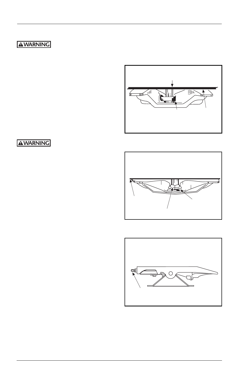
A direct visual inspection is required to assure proper coupling. Improper
coupling can pass the initial pull test. Sound is unreliable. Do not take for
granted that you are properly couple. Get out of the cab and look.
8.
Visually check to see that the kingpin
is in the fifth wheel locks, not
overhanging the fifth wheel or caught
in a grease groove. There should be no
gap between the trailer bolster plate
and the fifth wheel. (See FIGURE 1 and
FIGURE 2A.) Check for proper coupling
by looking into the throat of the fifth
wheel. Check the locks as shown in
FIGURE 1 for Type “A” locks and
FIGURES 2A and 2B for Type “B” locks.
If you do not obtain a
proper coupling, repeat
this sequence. Do not use any fifth wheel
which fails to operate properly.
9.
If your fifth wheel is equipped with a
manual secondary lock, engage it.
10. Using low gear, retract the landing
gear until unloaded. Then, shift to
high gear and continue cranking until
they are fully retracted. Fold down or
remove the crank handle and place it
in the crank handle holder.
11. Check the brake lines and light cord.
12. Remove the wheel blocks and continue
with pre-trip inspection.
WHEN LOCKED WITH LOCKS PROPERLY ADJUSTED,
THE YOKE WILL BE SEATED AS SHOWN AND THE
NUT AND WASHER WILL BE SNUG AGAINST THE
FIFTH WHEEL.
BOLSTER PLATE
FLUSH WITH
FIFTH WHEEL
LOCKS
CLOSED
KINGPIN PROTRUDES
BELOW LOCKS
PLUNGER
NO GAP
BOLSTER PLATE FLUSH WITH FIFTH WHEEL
WHEN LOCKED, SWINGING LOCK (JAW) MUST BE
AROUND KINGPIN AND LOCKING PLUNGER MUST
BE VISIBLE AS SHOWN AS VIEWED FROM THE
REAR OF THE TRACTOR.
TYPE ‘B’ LOCK
VIEW LOOKING INTO
THROAT OF FIFTH WHEEL
TYPE ‘A’ LOCK
TYPE ‘B’ LOCK
FIGURE 2A
FIGURE 1
FIGURE 2B