Maintenance procedures, Type “a” lock adjustment, Type “b” lock adjustment – SAF-HOLLAND XL-FW504 FW35-S09623 Series Fifth Wheel User Manual
Page 14
14
XL-FW504 Rev A
MAINTENANCE PROCEDURES
continued
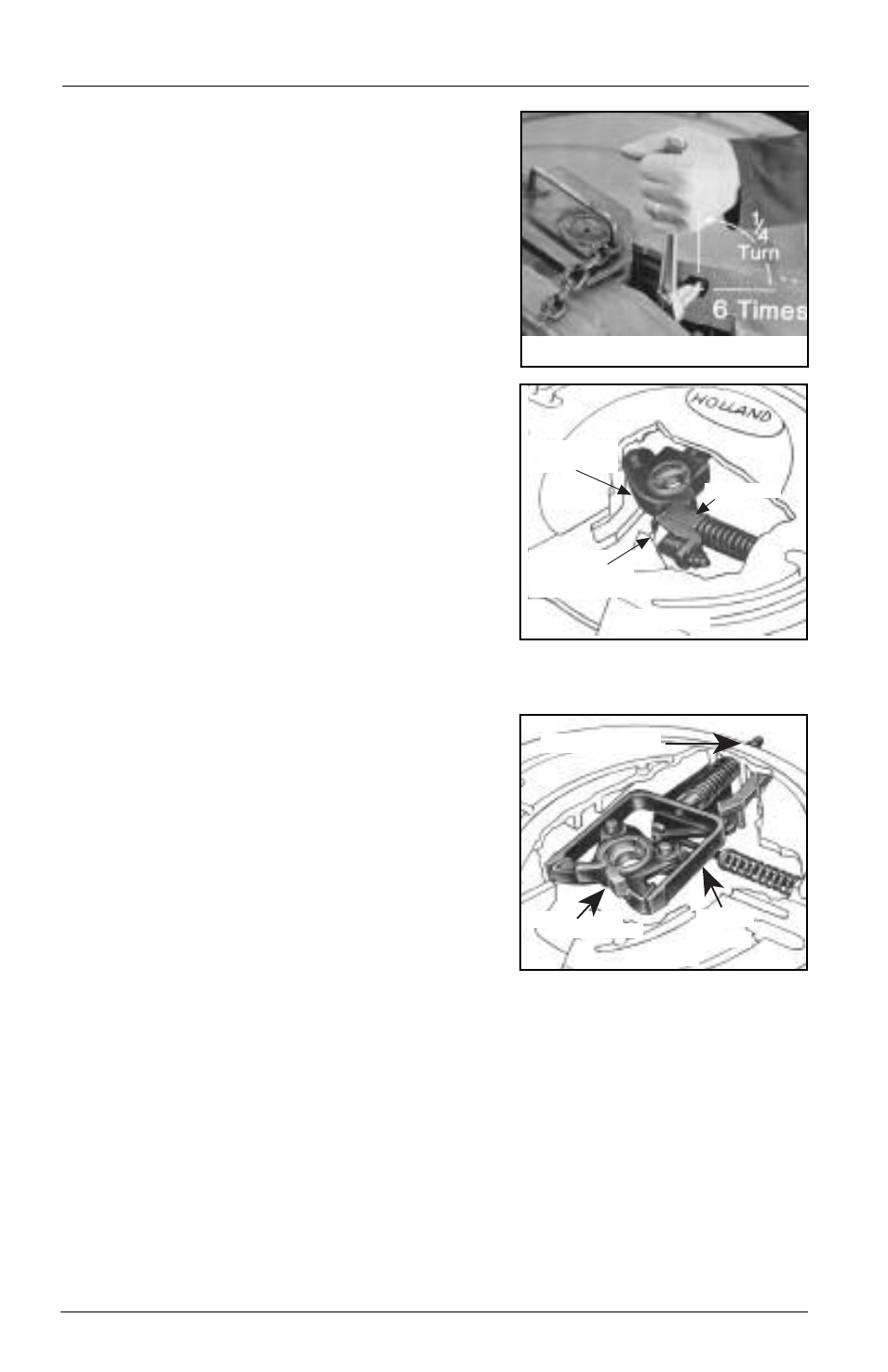
Type “A” Lock Adjustment
The lock adjustment screw is found in the crotch
on the right side as shown (FIGURES 1 & 2).
1.
Close the locks with the lock tester.
2.
Tighten the adjustment screw by turning
clockwise until tight, using a 1/2˝ Allen
wrench or Allen socket extension.
3.
Loosen the adjustment screw by turning it
counterclockwise 1
1
⁄
2
turns. The locks are
now properly adjusted.
4.
Verify this adjustment by locking and
unlocking several times.
Type “B” Lock Adjustment
1.
Close the locks and insert a 2˝ plug
(HOLLAND P/N TF-0237) in the locks.
2.
Check for a tight fit. The plug should be snug,
but you should be able to rotate it by applying
some force.
3.
If the plug fits loosely, tighten by rotating the
nut on the shank counterclockwise. It may be
necessary to tap the end of the yoke shank
lightly to allow the nut to seat against the top
plate.
4.
Repeat this procedure until the plug fits snug but can still be rotated. The locks are
now properly adjusted.
5.
Verify proper operation of the locking mechanism using the lock tester.
SPLIT LOCKS
LOCK ADJ. NUT
YOKE
SWINGING
LOCK
LOCK
ADJUSTMENT
SCREW
PLUNGER
FIGURE 1
FIGURE 2
FIGURE 3