Installation instructions, Sliding fifth wheel installation, Adjustment of sliding bracket locking plungers – SAF-HOLLAND XL-FW504 FW35-S09623 Series Fifth Wheel User Manual
Page 7: Installation of slide stops
XL-FW504 Rev A
7
INSTALLATION INSTRUCTIONS
continued
Sliding Fifth Wheel Installation
continued
Adjustment of Sliding Bracket Locking Plungers
The slide locking plungers are given a preliminary adjustment during factory assembly.
However, due to variations introduced during mounting (such as frame and material
tolerances) a final adjustment must be made at the time of installation.
Adjust the locking plungers at installation, after one month of service,
and at recommended maintainence intervals. by use of the adjusting
bolts provided on both sides. Failure to do so may result in accelerated wear of
components, lower service life, improper load transfer, or improper load distribution.
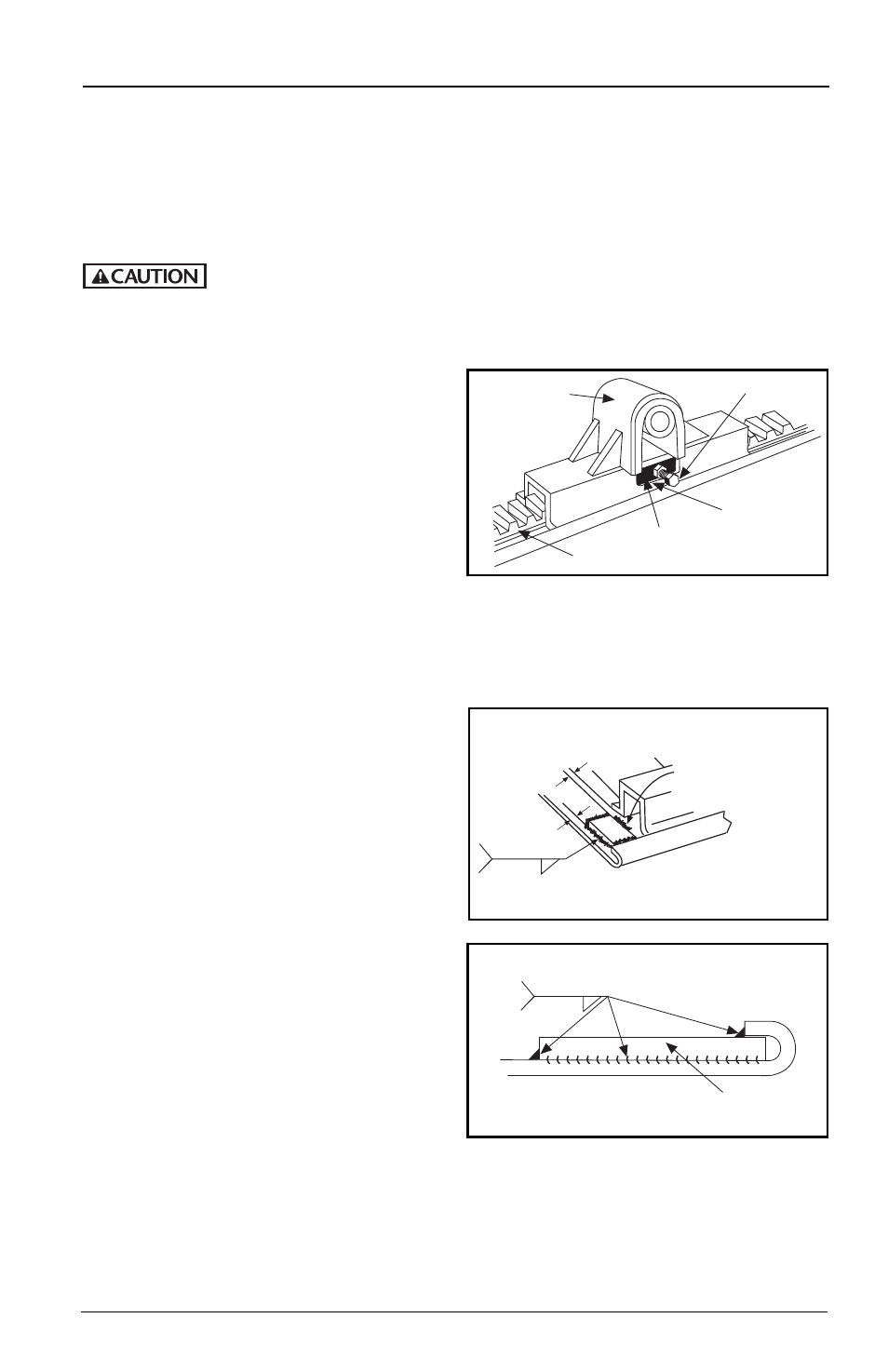
To adjust locking plungers:
1.
Loosen lock nut and turn adjusting bolt
out (counterclockwise). See FIGURE 7.
2.
Disengage and engage the locking
plungers. Check that the plungers are
securely seated without binding.
3.
Turn the adjusting bolt in (clockwise)
until it contacts the rack. Turn the bolt
an additional 1/2 turn then tighten the
locking nut securely.
Prior to proceeding with the installation of the sliding fifth wheel assembly, carefully
review the
“General Safety Information” section on page 2.
Installation of Slide Stops
1.
It is the responsibility of the installer
to insure that slide stops are installed
properly at all four corners of the
slider plate.
2.
Slide the bracket to the full rear
position and engage the plungers in
the rack.
3.
Locate rear stops under the curled
edge allowing some clearance to the
bracket (approximately 1/8˝). Clamp
in place. This should position the
stops approximately 1/4˝ to 1/2˝
from the edge of the rear of the plate,
see
FIGURES 8A and 8B.
4.
Slide bracket ahead out of the way
and weld the stops in place as shown
in FIGURES 8A and 8B. The welds
should be 5/16˝ fillet.
5.
Slide the bracket to the full rear
position and check for clearance.
Make sure the plungers on the sliding
bracket seat properly into the rack
with all teeth engaged.
6.
Repaint as required.
PLUNGER ADJ. BOLT
PLUNGER
RACK
BRACKET CAP
FIGURE 7
(Outside View)
1/8”
1/4”-1/2”
Locate and weld the
rear slide stops per steps
2 through 5 above.
Weld the forward side
in the center only
to avoid interference
with the bracket.
TYP.
5/16˝
Dimensions apply
after welding.
FIGURE 8A
TYP.
5/16˝
SLIDE STOP
FIGURE 8B (Rear End View)