Installation instructions, Stationary fifth wheel installation, Figure 1c – SAF-HOLLAND XL-FW504 FW35-S09623 Series Fifth Wheel User Manual
Page 4: Figure 1b (side view) figure 1a (end view), 4xl-fw504 rev a, Continued
4
XL-FW504 Rev A
INSTALLATION INSTRUCTIONS
continued
Stationary Fifth Wheel Installation
Prior to proceeding with the installation of the stationary fifth wheel assembly, carefully
review the “General Safety Information” section on page 2.
Bracket with Mounting Angle
(see Figure 1A, 1B, and 1C):
1.
Holland brackets with mounting
angle are provided with the bracket
welded in the center of a 36˝ long
angle with a 4˝ minimum
horizontal and 3-1/2˝ minimum
vertical leg size, and to a specific
tractor frame width. Verify that the
bracket and tractor frame width are
the same.
2.
In addition to the information
given in “Installation: General
Recommendations” on page 3, follow
the recommendations in FIGURE 1.
Bracket for Angle Mounting
(see Figure 1A, 1B, and 1C):
1.
Holland brackets for angle
mounting are intended to be
welded to mounting angles at the
time of installation.
2.
See “Installation: General Recommen-
dations” on page 3, for angle
thickness and material (use 4˝
minimum horizontal and 3-1/2˝
minimum vertical leg size).
The recommended length of
each mounting angle is 36˝
. It is
recommended that each angle
extend a minimum length of 18˝ forward of the fifth wheel pivot point, and not less
than 12˝ to the rear. If angles shorter than 36˝ are required, the special
recommendations of the tractor manufacturer should be obtained.
3.
In addition to the information given in
“Installation: General Recommendations,”
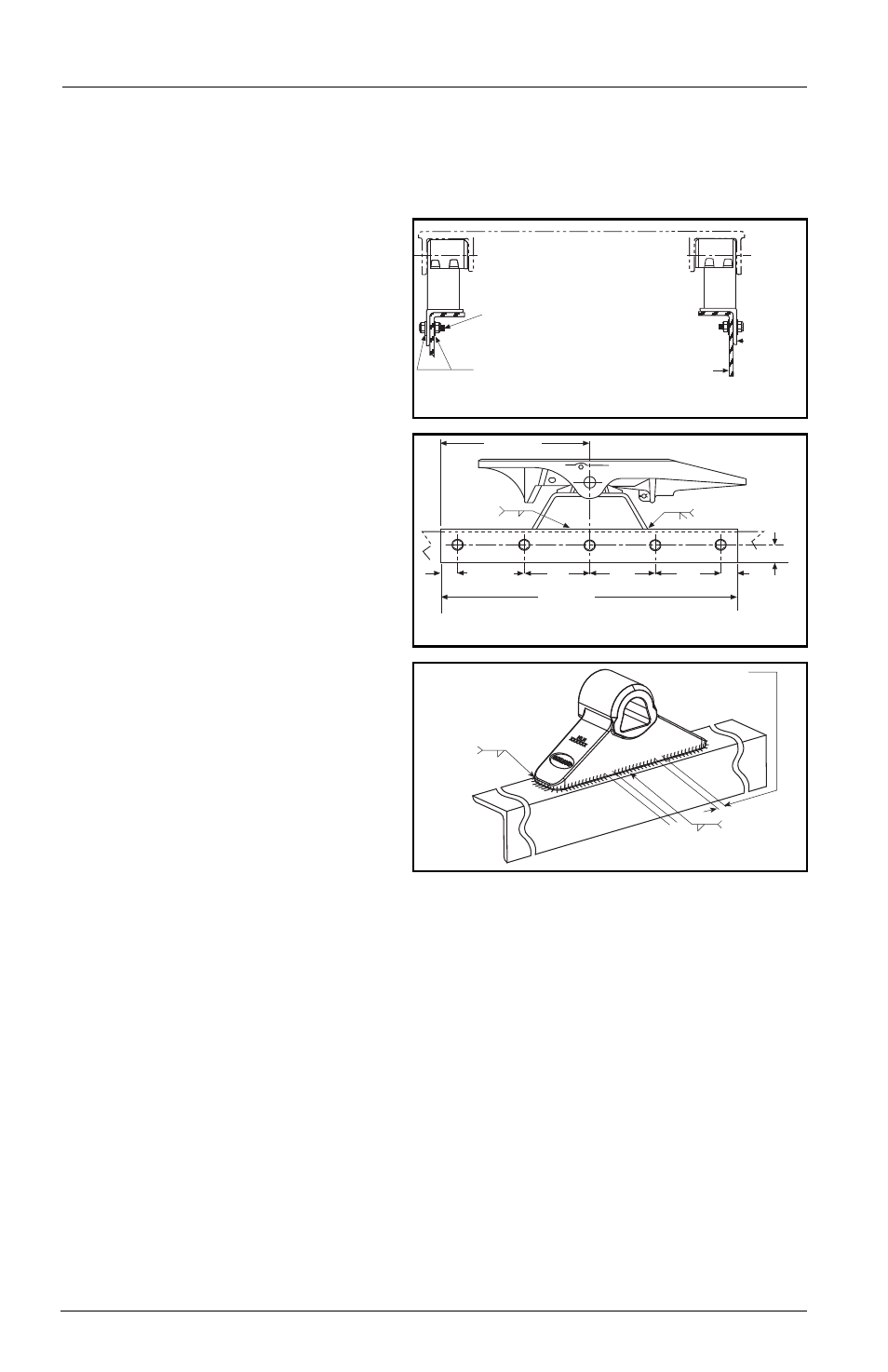
follow the recommendations given in FIGURES 1A, 1B, and 1C. The following
sequence is suggested for both fabricated and cast brackets:
A.
Securely position the mounting angle to the tractor frame.
B.
Bolt the angles to the tractor as shown in FIGURES 1A and 1B.
C.
Position the brackets on the angles and verify the correct spacing to mount
the fifth wheel.
D. For fabricated brackets (a welded asssembly), weld the bracket to the mounting
angle with 1/4˝ fillet welds on both sides, and 1/2˝ groove welds on both ends,
as shown in FIGURES 1A and 1B. The welds should be continuous around the
bracket and joined at the corners.
E.
For cast brackets (single piece), weld with 5/16˝ fillet weld, as shown in
FIGURE 1C. The welds must be continuous around the bracket ends.
The full length of the fifth wheel mounting
angle should seat flush on the truck frame
when mounting to prevent flexing of
mounting angle and to give uniform
weight distribution along truck frame rail.
5/8˝ diameter Grade 8 bolts minimum size,
tightening torque to bolt manufacturer
charts.
Hardened steel washers or flanged lock
nuts (5/8˝ diameter Grade “C” lock nuts).
HDN. STEEL WASHERS
TRUCK FRAME RAIL
See Chart 1
for minimum
mounting
angle
thickness
18.00˝ MIN.
36.00˝ MIN.
1.00˝ MIN.
DOUBLE PASS MIN.
BOTH ENDS
8.00˝ MAX. TYP.
(50.8mm)
2.00˝
(203.2mm)
1/4˝
BOTH SIDES
8.00
˝
(203.2mm)
(203.2mm)
8.00
˝
(203.2mm)
8.00˝
(914.4mm)
2.00˝
(50.8mm)
1/2˝
(457.2 mm)
3
5
/
16
GAP
1
/
4˝-1
/
2˝
in
4 places
5
/
16
Both ends
continuous
Both sides
center of
bracket
FIGURE 1C
(Cast Brackets Only)
WELDING DETAILS
FIGURE 1B (Side View)
FIGURE 1A (End View)