Amprobe AT-3500 Underground-Wire-Pipe-Locator User Manual
Page 10
8
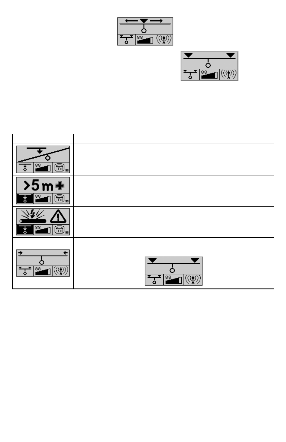
For Power and Radio signals, an estimated depth measurement can be taken as follow:
9.
Push control3 to select Power or Radio mode
a.
Move to one side of the suspected cable until the following symbol appears:
b.
Mark the spot
c.
Move to the other side until the symbol appears again
d.
Mark the spot
e.
Measure the distance between the two spots
f.
Divide the measurement by 2 to find the depth of the cable.
g.
ERRoR MESSAgES dURINg A dEPTH MEASUREMENT
Symbol
Meaning
For of one of the following reasons, the depth could not be measured:
•
The signal received was too weak or too irregular.
•
The receiver was not held steady enough during the measuring process.
The receiver was not positioned directly above the line at the beginning of the process.
The depth of the metallic conductor amounts to more than 5 m (16 ft).
The depth of the metallic conductor amounts to less than 30 cm (1 ft). Such conductors must
be specially marked in order to prevent damage during construction.
The receiver was moved too far to the left or right while making a rough estimate. Move in
the opposite direction until the following symbol appears:
TECHNICAL SPECIFICATIoNS
R-3500
The following parameters are specified for the R-3500 receiver:
Frequency ranges
• Range 1: radio
15 kHz to 23 kHz
• Range 2: power network
50 Hz / 60 Hz; optionally 100 Hz (can be adjusted by Amprobe service personnel)
• Range 3: transmitter
32.768 kHz
Sensitivity at a depth of 1m
• Range 1: radio
>20 µA
• Range 2: power network
>7 mA
• Range 3: transmitter
>5 µA
Dynamic response range
• Range 1: radio
120 dB
• Range 2: power network
135 dB
• Range 3: transmitter
120 dB
Depth determination
• Depth range
0.1 m … 5 m (4 in … 16 ft)