Amprobe AT-3500 Underground-Wire-Pipe-Locator User Manual
Page 8
6
Push
10.
O K
button to save the setting.
An audible sound is heard
•
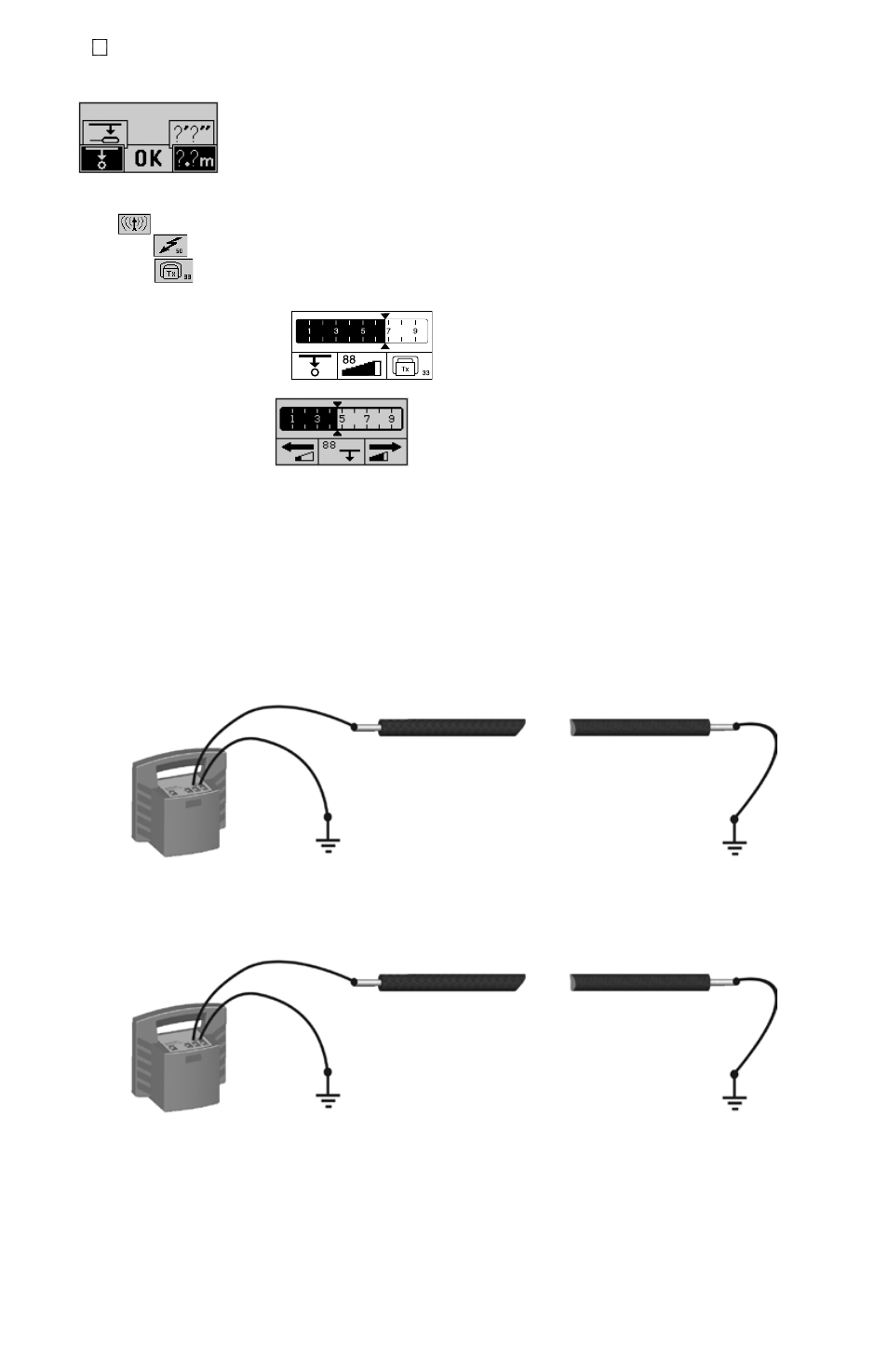
The display shows the main menu:
•
Push Control3 to select the mode of operation
11.
Radio
•
for locating cables carrying VLF re-radiated radio signals (No need for T-3500)
Power grid
•
for locating main power cables that carry electrical current (No need for T-3500)
Transmitter
•
for locating cables or pipes carrying the signal of the T-3500 transmitter.
Push Control2 twice rapidly to select automatic or manual sensitivity adjustment
12.
Automatic sensitivity adjustment:
•
Manual Sensitivity adjustment:
•
Push control1 to decrease sensitivity adjustment
i.
Push control3 to increase sensitivity adjustment
ii.
Push Control2 to start a depth measurement.
iii.
Hold the R-3500 receiver in an upright position in front of you as close to the ground as possible. Refer to Fig. 1.
13.
Receiver in line with the conductor
•
Maximum signal strength
Receiver perpendicular to the conductor
•
minimum signal strength
APPLICATIoNS ANd PRINCIPLES oF dIRECT CoUPLINg
Single-wire cables or pipes (with or without insulation against ground)
1.
The distance between the grounding rod and the ends of the connected lines should be as great as possible because return
current tends to flow through the earth into adjacent lines, which could result in their path being followed.
Single-wire cable with metallic screen and ground insulation
2.
Short circuit between internal conductor and screen at the end of the cable with ground at the beginning and end of the
cable as well.
Failure to make the connection as shown will result in current cancellation from the internal conductor and the return current
in the screen. Under certain circumstances this can prevent the cable from being detected.
Multiple-wire cable (internal conductor connected or disconnected) with metallic screen and grounding insulation
3.
Same application as in example 1
Metallic conduit (with or without insulation)
4.
the grounding rod and the conduit should be spaced as far apart as possible. Under certain circumstances, optimum
positioning of the grounding rod may require several attempts.
If a return wire is available
5.
the spacing of the return wire should correspond to at least 10 times the depth of the line being located.
Pair of wires (with or without screen) with short circuit at the end of the cable
6.
For twisted cable pair (with a length of lay of the twist greater or equal to the laying depth), the orientation of the cable can
be easily determined.