Amprobe AT-3500 Underground-Wire-Pipe-Locator User Manual
Page 7
5
UNPACkINg ANd INSPECTIoN
Your shipping carton should include:
1
R-3500 Receiver
1
T-3500 Transmitter
2
Measurement Cables
2
Alligator Clips
1
Grounding Rod
10
Battery IEC R6/AA Cell /Migon
6
IEC R20/ D Cell/ Mono
1
Nylon Bag
INTRodUCTIoN
The AT-3500 underground cable/pipe locator system is designed for the uncomplicated and user-friendly determination of the
location, orientation and depth of metallic lines (e.g. cable and pipe lines).
It can be used to probe areas for unknown lines or for locating specific lines.
The AT-3500 is distinguished by the following features:
Robust construction for use in poor weather and in harsh environments
Simple, user-friendly operation concept with a minimum number of controls
Reliable battery status indicator
oPERATIoN
Decide which mode of operation to use for your application
1.
Induction:
•
Transmitter’s signal is emitted through the integrated antenna and is thereby inductively coupled with
any metallic lines located within a certain radius.
Place the T-3500 transmitter on the site to be searched. Refer to Figs.1, 2.3&4.
i.
direct Connection:
•
Transmitter’s signal is directly coupled with a metallic line via the measurement cable which is
connected to the jacks on the front panel of the transmitter. Transmitter clamps, alligator clips or power socket adapters
(for example) may be used to connect the measurement cable to the lines.
Connect the T-3500 transmitter to the line to be located using the desired method. Refer to Figs 1, 2, 3, & 4
i.
T-3500 Transmitter
Push and Hold
2.
oN/oFF button to switch on the T-4000
Push
3.
Mode: C to select direct coupling or inductive coupling
Direct coupling
•
Green LED blinking: good (low-resistance) connection
Alternating red and green LED blinking: sufficient connection
Red LED blinking: poor/no (high-resistance) connection
Inductive Coupling:
•
Green LED blinking: induction mode is active
Push
4.
Signal Type: M to select Pulsed or Continuous signal
Pulsed Signal
•
is helpful when there is interference. Easier to distinguish from other signals.
Continuous Signal
•
is better to be used when taking a depth measurement
Green LED blinking indicates respective signal is on
Push
5.
Signal Strength: P to select low (0.1W) or High(0.5W) output signal strength
Low output (0.1W)
•
for normal tracing. Battery saving
High output(0.5W)
•
for long tracing
Green LED blinking indicates respective signal is on
R-3500 Receiver
Push and Hold the Control1 button
6.
Push briefly the ON/OFF button
7.
while holding control1 button
Listen for the audible signal before releasing control1
•
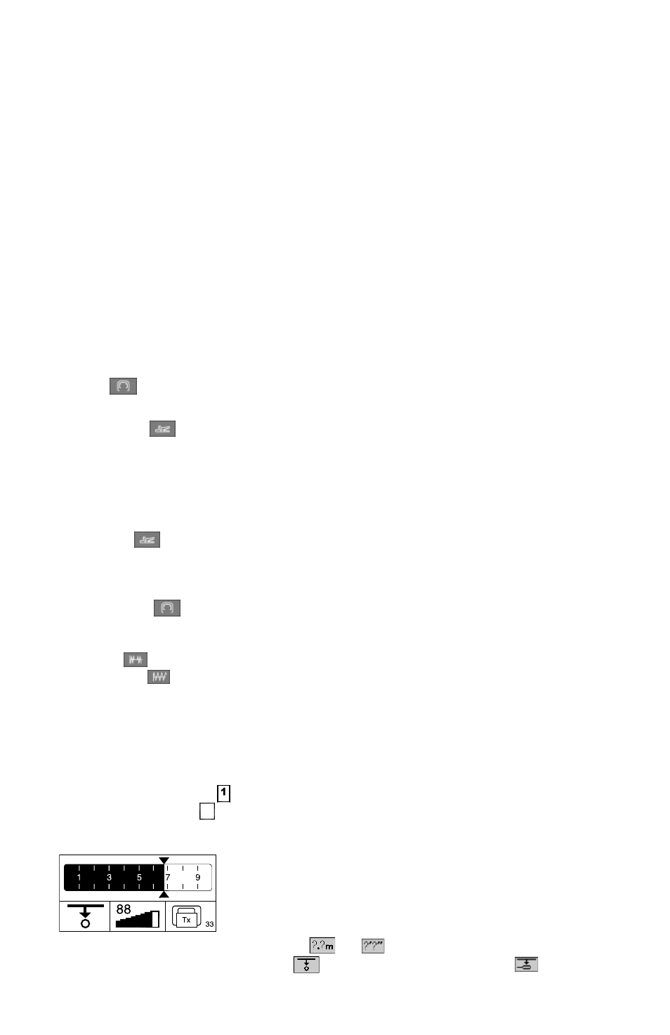
The display shows the following:
•
8.
Push control3 to select the unit of measurement (meter
8.
or ft
)
Push Control1 to select normal depth measurement
9.
or depth measurement using the mouse