A.7 fxo port pin assignments, A.8 fxs port pin assignments, A.9 e&m pin assignment – PLANET VIP-000 User Manual
Page 119
VIP User
’s Manual
Technical Specifications
105
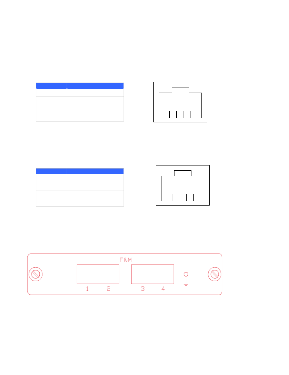
A.7 FXO Port Pin Assignments
The FXO Telephony Interface Module has 4 RJ11C/W modular jacks. The following diagram and
table show the assignments of the pin for the RJ11 port.
RJ-11 pin
Signal
1
Not connected
2
Tip
3
Ring
4
Not connected
A.8 FXS Port Pin Assignments
The FXS Telephony Interface Module has 4 RJ11C/W modular jacks. The following diagram and
table show the assignments of the pin for the RJ11 port.
RJ-11 pin
Signal
1
Not connected
2
Tip
3
Ring
4
Not connected
A.9 E&M Pin Assignment
The pin assignment for the current E&M (V2.0 and below) supports typeV 4W only. The description
below only applies to V2.0 and below E&M line module.
The pin assignment for each port starts from the left to the right
The color-coding scheme is just a reference; it depends upon the cable used.
And the I/P, O/P sense is from the line module side.
1
2
3
4
1
2
3
4