Inputting external synchronizing signals (genlock), Inputting external synchronizing signals, Genlock) – JVC GY-HC900STU 2/3" HD Connected Cam Studio Camcorder (Body Only) User Manual
Page 182: P182 [inputting external synchronizing, Signals (genlock)] )
Inputting External
Synchronizing Signals
(Genlock)
0
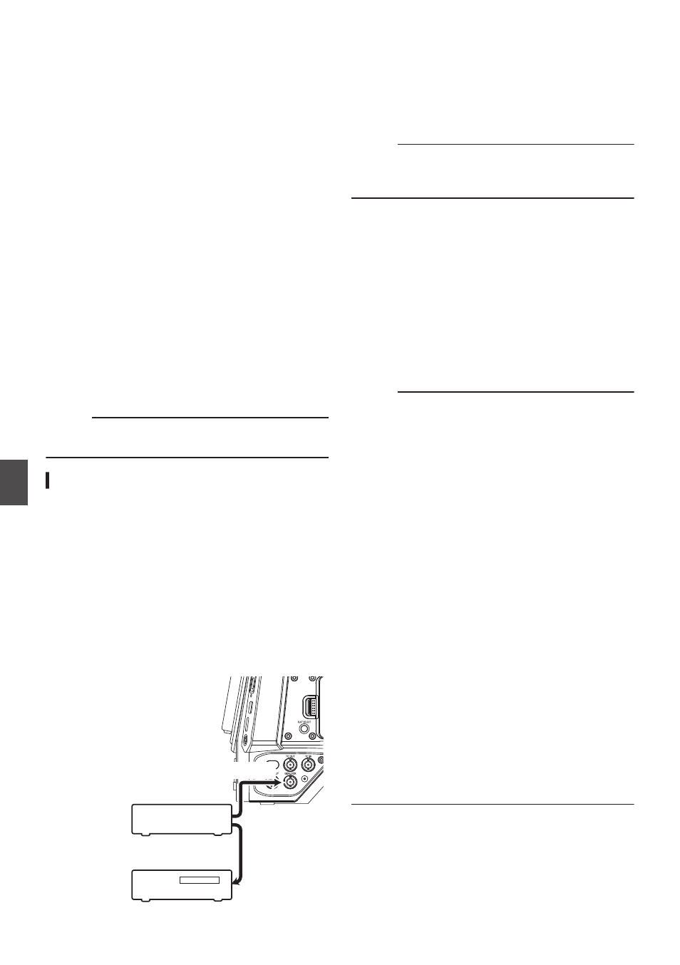
A [GENLOCK] terminal is available on the side
of the camera recorder.
0
You can input synchronizing signals from
FS-790 (sold separately) or FS-900 (sold
separately) that is connected to the accessory
connection terminal (68 pins) on the rear of the
camera recorder.
0
SDI signals (digital signals) can be input from the
[HD/SD SDI IN] terminal.
0
Input external synchronizing signals from the
[GENLOCK] terminal and [HD/SD SDI IN]
terminal, and synchronize the camera video with
the external signal.
0
Input external synchronizing signals from the
[GENLOCK] terminal, and synchronize the
camera video with the external signal.
0
The H (Horizontal) Phase of the camera
recorder’s video signals can be adjusted with
respect to the external synchronizing signals on
the [A/V Set]
B
[Video Set]
B
[Genlock Adjust]
screen.
Memo :
0
The genlock feature is only usable in the Camera
mode.
Genlock Signal Settings
For analog signal input
o
Synchronizing signal used
SD synchronizing
signal
: BB (Black Burst) signal
Supports SMPTE170M
(RS-170A)-NTSC
Supports ITU-R BT.470-6 PAL
HD synchronizing
signal
: HDTV tri-level synchronizing
signal
Supports SMPTE ST296-
HD720p
Supports SMPTE ST274-
HD1080i
.
GENLOCK
Video
Equipment
External Synchronizing Signal
External Synchronizing Signal
SYNC Signal
Generator
1
Set the camera recorder to the Camera
mode.
2
Set [Genlock Input] to “GENLOCK”.
Set [A/V Set]
B
[Video Set]
B
[Genlock Input] to
“GENLOCK”.
Memo :
0
Set to “Adapter” to input synchronizing signal
from the accessory connection terminal (68
pins) on the rear of this unit.
3
When in the standby or stop mode, input
synchronizing signals from the SYNC
signal generator to the [GENLOCK]
terminal.
0
When the camera recorder’s video is locking
to the external synchronizing signal, “Sync
Locking” appears on the screen.
0
After locking to the external synchronizing
signal is complete, the display disappears
and recording can be performed.
0
If there is genlock signal input but the signal
format is not supported, “Invalid Sync” is
displayed.
Memo :
0
If the frame rate in [
W
Frame & Bit Rate]/
[
Y
Frame & Bit Rate] in the [Record Format]
menu is set to “60p”, “60i” or “30p”, 59.94 Hz
synchronizing signals (vertical synchronization)
are input.
50 Hz/60 Hz synchronizing signals are not
synchronized.
0
If the frame rate of [
W
Frame & Bit Rate]/
[
Y
Frame & Bit Rate] in the [Record Format]
menu is set to “50p”, “50i”, or “25p”, 50 Hz
synchronizing signals (vertical synchronization)
are input.
59.94 Hz/60 Hz synchronizing signals are not
synchronized.
0
Do not connect or disconnect the input cable for
the synchronizing signals during recording or
playback
0
If the power is turned on during input of external
synchronizing signals, vertical oscillation may
occur. This is not a malfunction.
0
Signals such as VTR playback signals with
jitters may not be synchronized on this camera
recorder.
0
Only H (Horizontal) and V (Vertical) genlock
functions are available on this camera recorder.
It does not come with a lock function for SC (sub-
carrier). Color flash may occur during switching
such as when composite signals are used by a
switcher.
182
Inputting External Synchronizing Signals (Genlock)
Con
nectin
g Externa
l Devices