Adjustable precision shunt regulator, Typical performance characteristics – Diodes TL432 User Manual
Page 8
TL431/TL432
ADJUSTABLE PRECISION SHUNT REGULATOR
TL431
*SO-8 is a future package
Document number: DS35044 Rev. 6 - 2
8 of 14
April 2012
© Diodes Incorporated
Typical Performance Characteristics
(cont.)
0
1
2
3
4
5
6
0
1
2
3
4
5
6
7
8
9
10
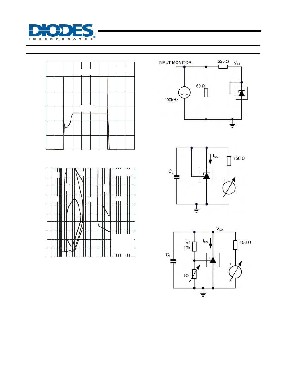
t Time ( s)
Pulse Response
μ
In
p
u
t an
d
O
u
tp
u
t V
o
lt
age
(
V
)
Out put
Input
T = 25 C
A
°
Test Circuit for Pulse Response
0
10
20
30
40
50
60
70
80
90
100
0.00001 0.0001 0.001
0.01
0.1
1
D
C -Load Capacitance - uF
Stability Boundary Conditions
L
I
-
C
at
hod
e C
ur
rent
-
m
A
KA
A V
= V
B V
= 5V
C V
= 10V
D V
= 15V
KA
REF
KA
KA
KA
Stable
Stable
Stable
D
C
C
B
B
A
10
T = 25 C
A
°
Test Circuit for Curve A
Test circuit for curves B, C, D
Test Circuit for Curves B, C, D
The device is stable under all conditions with a load capacitance not exceeding 50pF. The device is stable under all
conditions with a load capacitance between 5nF and 20nF. The device is stable under all conditions with a load capacitance
exceeding 300nF. With a cathode current not exceeding 5mA, the device is stable with any load capacitance.