Preparing for operation, Connecting the incremental encoder, 6commissioning – Pilz PNOZ ms3p HTL User Manual
Page 22: 2 preparing for operation, 1 connecting the incremental encoder
6.2
Preparing for operation
6
Commissioning
Pilz GmbH & Co. KG, Felix-Wankel-Straße 2, 73760 Ostfildern, Germany
Telephone: +49 711 3409-0, Telefax: +49 711 3409-133, E-Mail: [email protected]
6-2
6.2
Preparing for operation
6200
Preparing for operation
6-
6.2.1
Connecting the incremental encoder
Connecting the incremental encoder
6-
Drehzahlwaechter_Betriebsb_Inkremen
Follow the instructions below when connecting the incremental encod-
er:
The incremental encoder can be connected via an adapter (e.g.
PNOZ msi4p) or can be connected directly to the speed monitor.
The incremental encoder on connector X12 monitors axis 1; the incre-
mental encoder on connector X22 monitors axis 2.
Only use shielded cables for all connections
Always connect 0 V on the incremental encoder and speed monitor.
Position the terminating resistors on the signal lines as close as pos-
sible to the input on the speed monitor.
6.2.1.1
Connect the signals from the incremental encoder to the speed monitor
Connect the signals from the incremental encoder to the speed monitor
6-
Drehzahlwaechter_Betriebsb_Inkremen_24V-HTL_BA
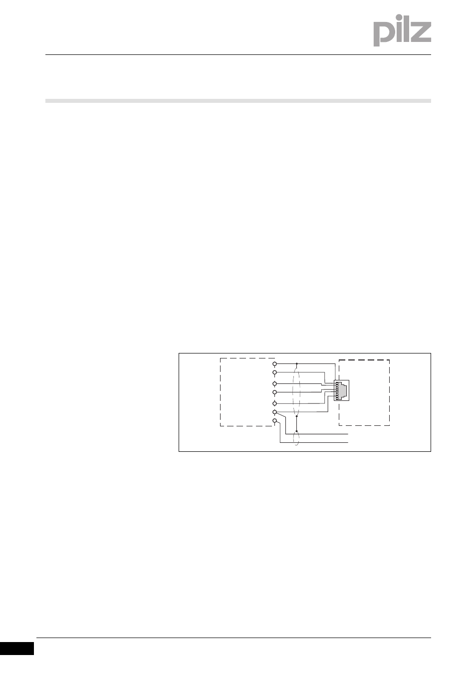
Encoder types: 24 V-HTL
Apply 24 VDC supply voltage to incremental encoder only
Do not terminate incremental encoder with Z0 = 120 Ohm
Fig. 6-1:
Connection to incremental encoder type 24 V-HTL
X12
X22
Speed monitor
24 V DC
0 V
2
4
5
7
8
A
/A
B
/B
24 V
0 V
Incremental
encoder