6 commissioning, 1 wiring, 2 connection – Pilz PNOZ m EF Multi Link User Manual
Page 14: Section 6, Commissioning, Wiring, Connection, 6commissioning
Commissioning
Operating Manual PNOZ m EF Multi Link
1003018EN02
14
6
Commissioning
6.1
Wiring
The wiring is defined in the circuit diagram of the PNOZmulti Configurator.
Note:
}
Information given in the "Technical details" must be followed.
}
The power supply must meet the regulations for extra low voltages with protective sep
aration.
}
2 connection terminals are available for each of the supply connections 24 V and 0 V.
This means that the supply voltage can be looped through several connections. The
current at each terminal may not exceed 3 A.
}
The max. cable length between two link modules on a connection with one link module
–
PNOZ ml1p <V2.0: 100 m
–
PNOZ ml1p from V2.0, PNOZ mml1p, PNOZ m EF Multi Link: 1000 m
}
Connect the inputs and outputs from two link modules with 4core shielded cable. The
cables must be twisted in pairs (see "Preparing for operation").
}
Note the crossover cabling, e.g. CA+ with CB+.
}
The cables must be classified into a minimum of Category 5 in accordance with ISO/
IEC 11801.
CAUTION!
Only connect and disconnect the expansion module when the supply
voltage is switched off.
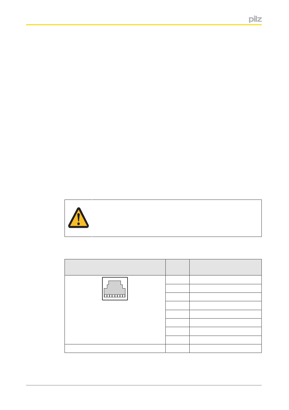
6.2
Connection
RJ45 socket
8pin
PIN
Layout
8 1
1
CA+
2
CA
3
CB+
4
n.c.
5
n.c.
6
CB
7
n.c.
8
n.c.
Shield
CGround