Press, Maintenance – Nexen LSCC-44 923632 User Manual
Page 8
FORM NO. L-21099-G-1209
8
MaInTenanCe
Nexen offers two different kits to aid in the maintenance of the LSCC: a facing kit and a repair kit (See REPAIR KITS
SECTION for part numbers). The facing kit contains friction facings, steel friction plates, and springs. The repair kit
includes O-Rings and bearings.
FaCInG KIT
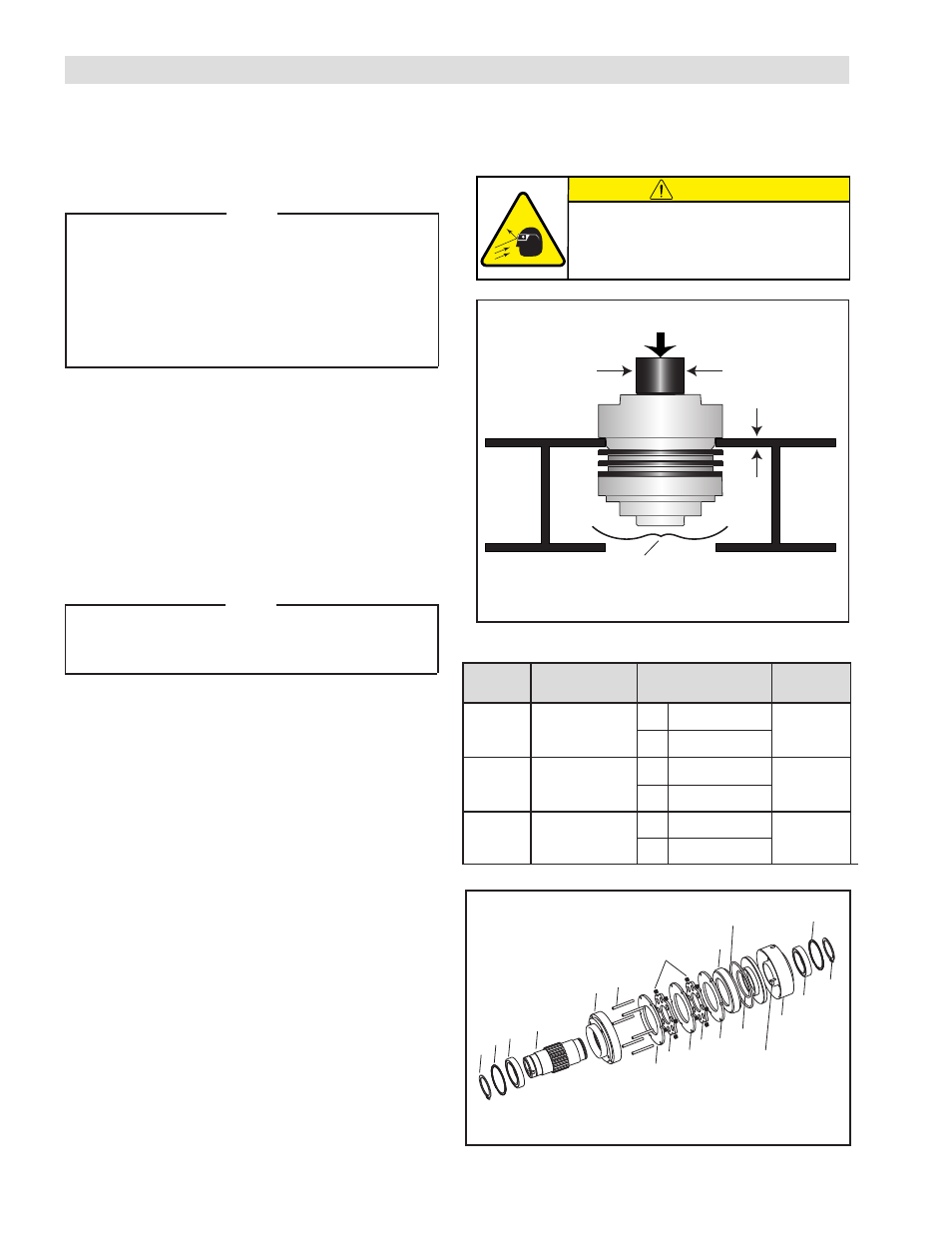
nOTe
The following tools are needed to press the unit
apart: a shaft, two sections of I-beam, and standard
retaining ring pliers.
To press the unit together, you will use a hollow shaft
fixture, making sure there is contact with the inner
race of the bearing while pressing (See Table 3 and
Figure 3).
D
isassembly
l
e
d
o
M
Ø
t
f
a
h
S
Ø
t
f
a
h
S
w
o
ll
o
H
b
e
W
s
s
e
n
k
c
i
h
T
2
3
-
C
C
S
L
m
m
8
.
4
3
-
4
.
5
2
]
"
7
3
.
1
-
0
0
.
1
[
D
I
]
"
4
.
1
[
m
m
5
.
5
3
m
m
6
.
6
]
"
5
2
.
0
[
D
O
]
"
0
1
.
2
[
m
m
3
.
3
5
4
4
-
C
C
S
L
m
m
1
.
3
4
-
3
.
1
4
]
"
0
7
.
1
-
5
2
6
.
1
[
D
I
]
"
0
8
.
1
[
m
m
7
.
5
4
m
m
2
.
0
1
]
"
0
4
.
0
[
D
O
]
"
0
6
.
2
[
m
m
0
.
6
6
4
5
-
C
C
S
L
8
.
0
5
-
1
.
1
4
]
"
0
0
.
2
-
2
6
.
1
[
D
I
]
"
5
2
.
2
[
m
m
2
.
7
5
m
m
6
.
8
]
"
4
3
.
0
[
D
O
]
"
0
5
.
3
[
m
m
9
.
8
8
Table 3
Figure 3
Shaft Ø
Web Thickness
Support the pilot end while pressing on the hub to prevent the
unit from falling to the floor.
Press
CAUTION
Working with spring loaded or tension
loaded fasteners and devices can cause
injury. Wear safety glasses and take the
appropriate safety precautions.
refer to Figure 3.
1. Remove the Retaining Ring (Item 14) from the Hub
Item 1) at the Air Chamber end of the unit.
2. Set the unit on the two pieces of I-beam with the Air
Chamber end of the unit resting on the I-beams.
3. Using an Arbor Press, align the proper shaft (as shown
in Table 3) with the Hub and apply pressure with the
Arbor Press.
nOTe
Support the pilot end of the unit as the Hub is
pressed out to prevent the unit from falling to the
floor.
4. Remove the Friction Facings (Item 4) and Friction
Plates (Item 5) along with the springs from the drive
pins.
R
eassembly
5. Using a degreaser, clean both ends of the unit removing
all facing dust and grease before reassembly.
6. Reassemble the unit (Pilot end down) by replacing (in
order) the Facings, Friction Plates, and Springs on the
Drive Pins.
7. Position the unit in an Arbor Press and place the Air
Chamber/Piston combination on top of the Hub.
8. Holding the Air Chamber (Item 3) and the hollow shaft
on top of the Hub (Item 1), press the Air Chamber (Item
3) back onto the Hub using the hollow shaft fixture.
9. Insert the Retaining Ring (Item 14) back onto the Hub
(Item 1).
10. Verify that the unit is functional by applying air to the
unit and watching it engage and disengage.
14
6
1
2 15
4
17
5 4
5 4
10
13
19
7
3
6
14
12
7
Figure 4
- LSCC-44 923567 LSCC-44 923595 LSCC-44 923631 LSCC-44 923619 LSCC-44 923569 LSCC-32 923605 LSCC-32 923583 LSCC-32 923582 LSCC-32 923603 LSCC-44 923586 LSCC-44 923556 LSCC-44 923568 LSCC-44 923563 LSCC-44 923585 LSCC-44 923587 LSCC-44 923581 LSCC-32 923566 LSCC-32 923607 LSCC-44 923555 LSCC-44 923557 LSCC-44 923562 LSCC-44 923554 LSCC-44 923550 LSCC-44 923620 LSCC-44 923621 LSCC-44 923590 LSCC-54 923604 LSCC-54 923615 LSCC-54 923588 LSCC-54 923576 LSCC-54 923617 LSCC-32 923564 LSCC-32 923565 LSCC-32 923553 LSCC-32 923622 LSCC-44 923628 LSCC-44 923551 LSCC-44 923552 LSCC-32 923559 LSCC-32 923560 LSCC-54 923577 LSCC-54 923578