Nexen 4H35P 923512 User Manual
Page 5
5
FORM NO. L-20007-K-0913
INSTALLATION
4H
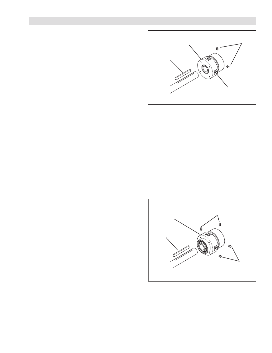
Refer to Figure 1.
1. Secure the Driving Shell (Item 17) to a bearing supported
sheave or flywheel.
NOTE: The Driving Shell (Item 17) must be concentric
to the machine shaft within 0.010 T.I.R. to
prevent abnormal wear of the outer plate
teeth.
2. Slide the Driving Shell and bearing supported sheave
or flywheel onto the machine shaft.
3. Insert the customer supplied key into the machine
shaft.
NOTE: When assembling the Driving Shell (Item 17),
fit each Outer Plate (Item 5) into the Driving
Shell. Forcing the Driving Shell over the Outer
Plates will damage the teeth of the Outer
Plates.
4. Slide the Multiple Disc Clutch onto the machine
shaft.
5. Install and tighten the two Set Screws (Item 18) securing
the Multiple Disc Clutch to the machine shaft.
4HP
Refer to Figure 2.
1. Secure a sheave or flywheel to the Driving Shell (Item
17) of the Multiple Disc Clutch.
2. Insert the customer supplied key into the machine
shaft.
3. Slide the Multiple Disc Clutch onto the machine
shaft.
4. Install and tighten the four Set Screws (Item 18) securing
the Multiple Disc Clutch to the machine shaft.
Customer
Supplied key
Driving Shell
(Item 17)
Outer Plate
(Item 5)
Set Screw
(Item 18)
FIGURE 1
Customer
Supplied key
Set Screw
(Item 18)
Driving Shell
(Item 17)
Set Screw
(Item 18)
FIGURE 2
- 4H35P 923511 4H35P 923500 4H35P 923501 4H40P 923601 4H40P 923611 4H40P 923600 4H40P 923613 4H40P 923612 4H40P 923614 4H70P 924012 4H70P 924013 4H70P 924002 4H70P 924000 4H70P 924014 4H70P 924004 4H70P 924001 4H45P 923702 4H45P 923712 4H45P 923700 4H45P 923701 4H45P 923713 4H50P 923809 4H50P 923801 4H50P 923803 4H50P 923812 4H50P 923800 4H50P 923804 4H50P 923802 4H50P 923813 4H60P 923902 4H60P 923900 4H30P 923412 4H30P 923400 4H30P 923413 4H30P 923401 4H35 917700 4H40 917800 4H70 918200 4H45 917900 4H50 918000 4H60 918100 4H60 918101 4H30 917600 4H30 918300 4H35 918400 4H40 918500 4H45 918600 4H70 918900 4H30P 919000 4H35P 919100 4H40P 919200 4H45P 919300 4H50P 919400 4H60P 919500 4H70P 919600 4H30 921100 4H30P 921100 4H35 921200 4H35P 921200 4H40 921300 4H40P 921300 4H45 921400 4H45P 921400 4H50 921500 4H50P 921500 4H60 921600 4H60P 921600 4H70 921700 4H70P 921700