Nexen DPC-11T 961200 User Manual
Page 12
9
FORM NO. L-20070-F-1209
PARTS REPLACEMENT (continued)
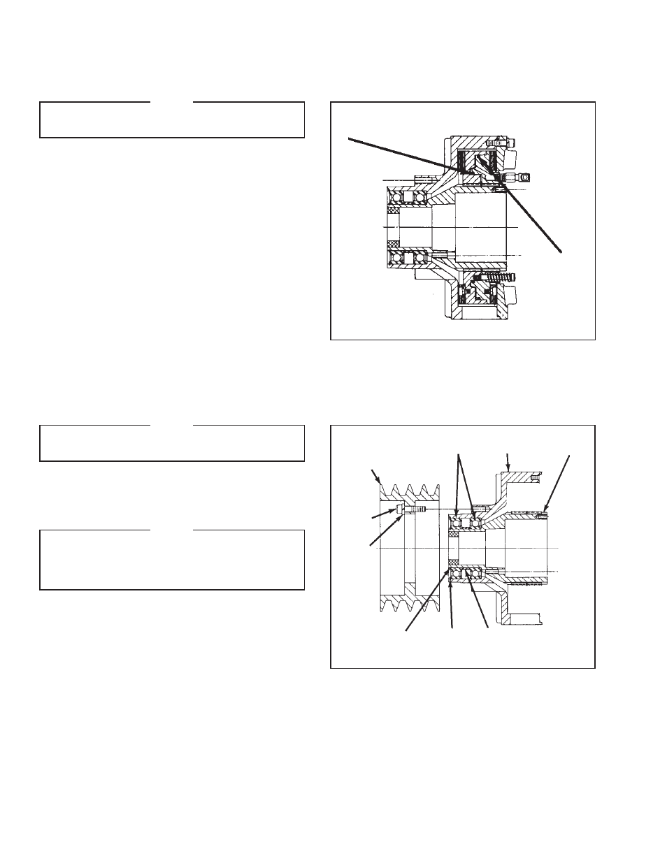
O-RINGS (ITEMS 8 & 9)
NOTE
Replace O-rings (Items 8 & 9) if there are
noticeable air leaks, or a loss of torque.
REFER TO FIGURE 8.
1. Proceed with Steps 1 through 7 for the Friction
Facing Replacement.
2. Remove O-rings (Items 8 & 9), and clean o-ring
contact surfaces with fresh safety solvent.
3. Lubricate new O-rings, and o-ring contact surfaces
with fresh o-ring lubricant.
4. Install new O-rings (Items 8 & 9).
5. Reverse Step 1 to reassemble the DPC Clutch-
noting chalk alignment marks- and tighten all screws
to the recommended torque (See Table 4).
9
8
FIGURE 8
BEARINGS (ITEM 16)
NOTE
DPC Clutch Bearings are pre-lubricated, sealed,
and do not require further lubrication.
REFER TO FIGURE 9.
1. Disconnect the air supply line, and Hose Assemblies
at the Piston/Drive Disc Elbow Fittings.
NOTE
If the DPC Clutch is shaft mounted, remove
the Rotary Air Union Cap (Item 25). On through
shaft installation, remove the Elbow Fittings
(Item 20) from the shaft.
2. Loosen the Q.D. Bushing by first removing the Q.D.
Bushing Pull-Up Bolts and Lockwashers. Then insert
Pull-Up Bolts into tapped Q.D. Bushing removal
holes and alternately and evenly tighten each until the
Splined Hub (Item 1) is loose on the Q.D. Bushing.
3. Wedge a screwdriver into the saw-cut in the Q.D.
Bushing to loosen the Q.D. Bushing from the Shaft;
then remove the “DPC” Clutch.
4. Remove Cap Screws (Item 28), and Lockwashers
(Item 27), and Sheave (Item 26) in mounted on the
DPC Clutch.
5. Proceed with steps 1 through 7 for the Friction
Facing replacement.
16
5
1
26
28
27
17
18
7
FIGURE 9