Nexen DPC-11T 961200 User Manual
Page 6
3
FORM NO. L-20070-F-1209
PILOT MOUNT CLUTCH
REFER TO FIGURE 2.
1. Install Support Bushing if required.
2. Thoroughly inspect tapered bore of the Splined Hub
and tapered surface of the Q. D. Bushing. Remove
any dirt, grease, or foreign material.
NOTE
Do not use lubricants when installing the Q.D.
Bushing.
3. Install Q. D. Bushing into Splined Hub, aligning
untapped holes on Q. D. Bushing Flange with
tapped holes in Splined Hub.
NOTE
Do not strike Q. D. Bushing to “SET” it in the
tapered bore.
4. Loosely insert Pull-Up Bolts and Lockwashers into
Q. D. Bushing, and tapped holes of Splined Hub.
NOTE
Do not use lubricants or thread locking
compounds on Pull-Up Bolts.
5. Measure runout of Motor Shaft. Runout must not
exceed 0.002 T.I.R. (Total Indicator Reading)
6. Insert Key into Motor Shaft Keyway.
7. Slide “DPC” Clutch onto Motor Shaft.
8. Alternately, and evenly tighten Pull-Up Bolts to
recommended torque (See Table 1).
NOTE
Do not over tighten Pull-Up Bolts. If excessive
tightening torque is applied, bursting pressure
is created in the Splined Hub.
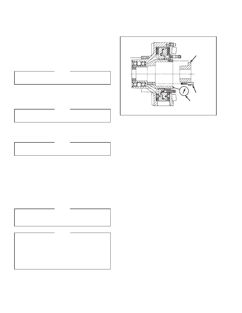
NOTE
Runout is minimized if a Dial Indicator is
used as the Q. D. Bushing Pull-Up Bolts are
tightened. Place contact tip of Dial Indicator
on the machined surface of the Splined Hub to
measure runout. Runout on this surface must
be within 0.003 T.I.R. when the Pull-Up Bolts
are tightened.
Q.D. Bushing
Pull-Up
Bolts
Dial
Indicator
FIGURE 2
INSTALLATION (continued)