Nexen DPC-11T 961200 User Manual
Page 8
5
FORM NO. L-20070-F-1209
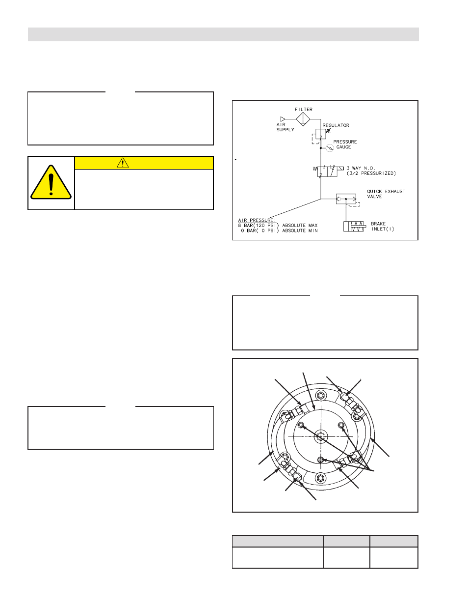
SHAFT END MOUNTING
REFER TO FIGURE 4.
1. Install two Elbow Fittings (Item 20) into the Rotary
Air Union Cap (Item 25).
2. Install an Adaptor Fitting (Item 19) and Elbow Fitting
(Item 20) into each air inlet of the Piston/Drive Disc
(Item 2).
3. Using Cap Screws (Item 24), attach the Rotary
Air Union Cap (Item 25) to the tapped holes of the
Splined Hub (Item 1).
NOTE
The Rotary Air Union Cap air outlets must be
aligned at approximately 60
O
to the Piston/
Drive Disc air inlets for proper Hose (Item 22)
connection.
4. Tighten the Cap Screws (Item 24) to the
recommended torque (See Table 3).
5. Install Hoses (Item 22).
6. Install the Rotary Air Union (Item 21).
7. Connect air supply to the Rotary Air Union.
AIR CONNECTIONS
TABLE 3 Recommended Tightening Torques
Description
DPC-9T
DPC-11T
Cap Screw (Item 24)
13 ft-lbs
[18 Nm]
13 ft-lbs
[18 Nm]
20
25
19
20
24
22
20
19
20
2
22
FIGURE 4
NOTE
For quick response, Nexen recommends a quick
exhaust valve and short air lines between the
Control Valves and the unit. Align the air inlet
ports to a down position to allow condensation
to drain out of the air chambers of the product.
All Nexen pneumatically actuated devices require clean and
dry air, which meets or exceeds ISO 8573.1:2001 Class
4.4.3 quality.
The following are common air supply schemes used with
this product. These are examples and not an all-inclusive
list. All air circuits to be used with this product must be
designed following EN983 guidelines.
CAUTION
Low air pressure will cause slippage and
overheating. Excessive air pressure will
cause abrupt starts and stops, reducing
product life.
NOTE
Do not use rigid pipe or tubing for this connection.
For fast engagement and disengagement,
connect air controls as close to the DPC Clutch
as possible. Where long air lines are required,
use a quick exhaust valve.