Nexen DPB-09T 960003 User Manual
Page 6
6
FORM NO. L-20094-D-0210
BRAKE
NOTE
Flange mounting of the DPB Brake is not recommended.
Tapped holes in the DPB Brake’s Splined Hub (Item
35) are used to connect the brake to a torque pin or
torque arm.
1. Thoroughly inspect tapered bore of Flanged Hub (Item
36) and tapered surface of Q.D. bushing. Remove any
dirt, grease, or foreign material.
NOTE: Do not use lubricants when installing O.D.
bushing.
2. Install Q.D. bushing into flanged hub, aligning untapped
holes in Q.D. bushing flange with tapped holes in flanged
hub.
3. Loosely insert pull-up bolts and lockwashers into Q.D.
bushing and tapped holes of flanged hub.
NOTE: Do not use lubricants or thread locking
compounds on pull-up bolts.
4. Insert customer supplied key into motor shaft.
5. Slide DPB Brake onto motor shaft.
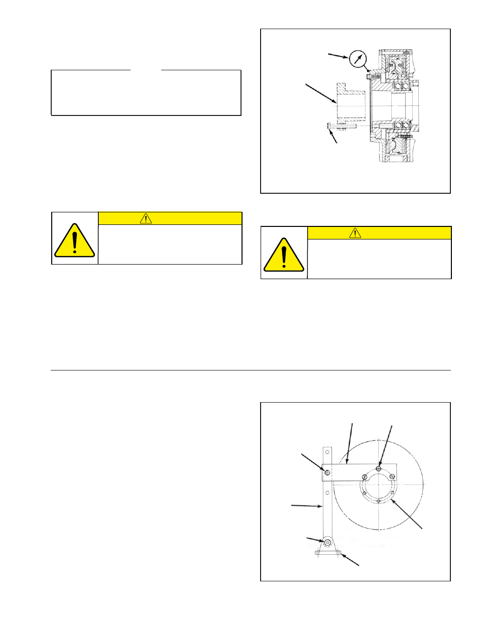
FIGURE 2
Dial Indicator
Q.D. Bushing
Pull-up
Bolts
TORQUE ARM
Refer to Figure 3.
1. Using Cap Screws (Item 42) and Lockwashers (Item
43) secure Torque Arm (Item 37) onto Splined Hub
(Item 35).
2. Tighten Cap Screws (Item 42) to 119 ft. lbs. torque.
3. Using Cap Screws (Item 40) and Lock Nut (Item 44),
secure Extension Arm (Item 37) to Torque Arm (Item
38).
4. Tighten Lock Nut (Item 44) to 70 ft. lbs. torque.
5. Using Cap Screw (Item 41) and Lock Nut (Item 45),
attach Extension Arm (Item 38) to Bracket (Item 39).
6. Tighten Lock Nut (Item 45) to 200 ft. lbs. torque.
7. Using four customer supplied 7/16-UNC bolts, secure
Bracket (Item 39) to a firm support.
42
43
FIGURE 3
37
40
44
38
41
45
39
35
CAUTION
Do not over tighten pull-up bolts. If
excessive tightening torque is applied,
bursting pressure is created in flanged
hub.
CAUTION
Do not strike O.D. bushing to
"set" it in the tapered bore.
6. Alternately and evenly tighten pull-up bolts to
recommended torque (See Table 1).
NOTE: Runout is minimized if a dial indicator is used
as the Q.D. bushing pull-up bolts are tightened.
Place contact tip of dial indicator on smooth
surface of Flange Mount Disc (Item 5) to
measure runout. Runout on this surface must
not exceed 0.003 T.I.R. when pull-up bolts are
tightened (See Fig. 2).
INSTALLATION (continued)